CHAPTER 1
SET-UP
1-19
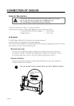
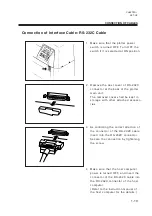
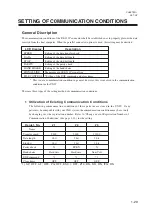
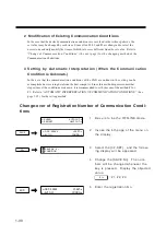
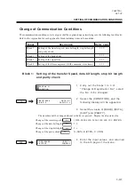
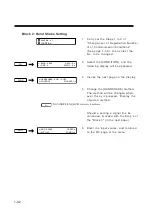
Connection of Interface Cable: RS-232C Cable
1
Make sure that the plotter power
switch is turned OFF. Turn OFF the
switch if it is selected at ON position.
2
Remove the dust cover of RS-232C
connector at the back of the plotter
main unit.
The removed cover shall be kept in
storage with other attached accesso-
ries.
3
As confirming the correct direction of
the connector of the RS-232C cable,
insert into the RS-232C connector.
Secure the connection by tightening
the screw.
4
Make sure that the host computer
power is turned OFF, and insert the
connector of the RS-232C cable into
the RS-232C connector of the host
c o m p u t e r .
(Refer to the instruction manual of
the host computer for the details.)
CONNECTION OF CABLES
Summary of Contents for cg-100AP
Page 16: ...xiv ...
Page 70: ...1 54 ...
Page 108: ...2 38 ...
Page 145: ...CHAPTER 4 SELF DIAGNOSIS FUNCTION 4 9 DEMONSTRATION PATTERN 1 2 Demonstration Pattern 1 ...
Page 146: ...4 10 Demonstration Pattern 2 ...
Page 173: ...CHAPTER 6 APPENDIX 6 13 Table of 82 special character codes supported ...
Page 179: ...D200310MAC 2 00 09061999 ...
Page 180: ... MIMAKI ENGINEERING CO LTD 1999 6 Printed in japan ...

