background image

OM-363 Page 38

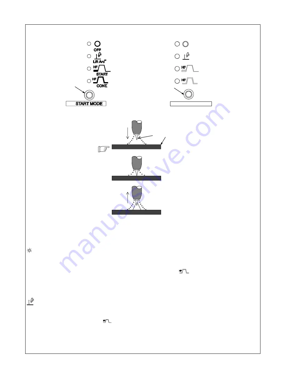
4-9. Start Mode

1

Start Mode

For SMAW welding, press button to toggle

LED to Off position.

For GTAW welding, use control to select

Off for no HF, Lift-Arc

, HF for arc starting

only, or continuous HF.

Application:

When Off is selected, use the scratch

method to start an arc for both the SMAW

and GTAW processes.

When Lift-Arc is selected, start arc as

follows:

2

TIG Electrode

3

Workpiece

Touch tungsten electrode to workpiece at

weld start point, enable output with torch

trigger, foot control, or hand control. 

Hold

electrode to workpiece for 1-2 sec-

onds

, and slowly lift electrode. An arc will

form when electrode is lifted.
Shielding gas begins to flow when elec-

trode touches work piece.
Normal open-circuit voltage is not present

before tungsten electrode touches work-

piece, only a low sensing voltage is pres-

ent between electrode and workpiece.

The solid state output contactor does not

energize until after electrode is touching

workpiece. This allows electrode to touch

workpiece without overheating, sticking,

or getting contaminated.

Application:

Lift-Arc is used for the DCEN GTAW pro-

cess when HF Start method is not per-

mitted, or to replace the scratch method.

When HF Start is selected, start arc as

follows:

High frequency turns on to help start arc

when output is enabled. High frequency

turns off when arc is started, and turns on

whenever arc is broken to help restart arc.

Application:

HF Start is used when the DCEN GTAW

process is required.

When HF Continuous is selected, start

arc as follows:

High frequency turns on when output is

energized and remains on for duration of

weld.

Application:

HF Continuous is used when the AC

GTAW process is required.

NOTE:

 Lit LED indicates selected mode.

When Output Selector switch position

changes, LED may change position,

based upon last selection.

NOTE: 

Some start methods may not be

available for all processes.

2

 2

Seconds

“Touch”

Do NOT Strike Like A Match!

3

Lift-Arc

 Start Method

1

(CE Nameplate)

1

Summary of Contents for Syncrowave 250 DX

Page 1: ...e at www MillerWelds com Processes Description TIG GTAW Welding Stick SMAW Welding Arc Welding Power Source OM 363 213117Z 2008 12 Syncrowave 250 DX 350 LX ESPA OL FRAN AIS ENGLISH CE And Non CE Model...

Page 2: ...tinue the tradition They re just as committed to providing equipment and service that meets the high standards of quality and value established in 1929 This Owner s Manual is designed to help you get...

Page 3: ...IG HF Impulse DCEN Direct Current Electrode Negative 16 3 14 Front Panel Display For TIG AC 17 3 15 Optional Cooler Connections 18 3 16 Stick Connections 19 3 17 Front Panel Display For Stick DCEP Dir...

Page 4: ...54 SECTION 8 HIGH FREQUENCY 57 8 1 Welding Processes Requiring High Frequency 57 8 2 Incorrect Installation 57 8 3 Correct Installation 58 SECTION 9 SELECTING AND PREPARING A TUNGSTEN FOR DC OR AC WE...

Page 5: ...yncrowave 350 LX 907409 Council Directives 2006 95 EC Low Voltage 2004 108 EC Electromagnetic Compatibility 2006 42 EEC Machinery Directive Standards IEC 60974 1 Arc Welding Equipment Welding Power So...

Page 6: ......

Page 7: ...scaffolds when in cramped positions such as sitting kneeling or lying or when there is a high risk of unavoid able or accidental contact with the workpiece or ground For these conditions use the follo...

Page 8: ...s unless they are properly prepared according to AWS F4 1 see Safety Standards Do not weld where the atmosphere may contain flammable dust gas or liquid vapors such as gasoline Connect work cable to t...

Page 9: ...ans Keep all doors panels covers and guards closed and securely in place Have only qualified persons remove doors panels covers or guards for maintenance as necessary Reinstall doors panels covers or...

Page 10: ...rk NY 10036 8002 phone 212 642 4900 website www ansi org Standard for Fire Prevention During Welding Cutting and Other Hot Work NFPA Standard 51B from National Fire Protection Association P O Box 9101...

Page 11: ...lammables away from welding Do not weld near flammables 3 2 Welding sparks can cause fires Have a fire extinguisher nearby and have a watchperson ready to use it 3 3 Do not weld on drums or any closed...

Page 12: ...On Off Percent Direct Current Balance Control Maximum Cleaning Maximum Penetration Electrode Positive Electrode Negative Final Slope Meter Single Phase U0 Rated No Load Voltage Average U1 Primary Vol...

Page 13: ...ning gear gas cylinders or any other accessories Use equipment of adequate capacity to lift and support unit If using lift forks to move unit be sure forks are long enough to extend beyond opposite si...

Page 14: ...Models Rated Welding Output PFC Amperes Input at AC Balanced Rated Load Output 50 60 Hz Single Phase KVA KW Amperage Range Max OCV Uo Rated Peak Starting Voltage Up 200V 220V 230V 400V 440V 460V 520V...

Page 15: ...C 60 Duty Cycle No PFC 82 3 0 45 1 6 41 1 4 35 1 2 17 6 59 8 6 29 3 310A 80V 15 KV With PFC 61 45 9 34 25 1 31 22 8 26 23 2 12 06 11 2 8 11 39 3 310A 80V 15 KV NEMA Class II 40 250 Amperes 30 Volts AC...

Page 16: ...perage or duty cycle before welding NOTICE Exceeding duty cycle can damage unit and void warranty Overheating 0 15 A OR Reduce Duty Cycle Minutes duty1 4 95 190 276 4 Minutes Welding 6 Minutes Resting...

Page 17: ...s fall between the curves shown 3 7 Volt Ampere Curves A For 250 DX Models Non CE Models CE Models 205 631 205 632 0 50 100 150 200 AMPS 250 300 350 400 450 0 50 100 150 200 AMPS 250 300 350 400 450 0...

Page 18: ...90 277 ST 190 278 The volt ampere curves show the minimum and maximum voltage and amperage output capabilities of the welding power source Curves of other settings fall between the curves shown 350 Am...

Page 19: ...LDING can cause Electromagnetic Interference Do not use worn dam aged undersized or poorly spliced cables Weld Output Terminals Turn off power before connecting to weld output terminals Total Cable Co...

Page 20: ...10 volts output GND K Chassis common The remaining sockets are not used 3 10 Shielding Gas Connections And 115 Volts AC Duplex Receptacle Ref 803 588 B Ref 803 585 B Ref 157 858 Turn Off power before...

Page 21: ...ut terminal 6 Gas Out Connection Connect torch gas hose to gas out fitting Tools Needed 11 16 21 mm 1 2 3 4 5 6 3 12 TIG Connections With A One Piece Air Cooled Torch 803 615 B Turn Off power before m...

Page 22: ...ative 1 Front Panel Correct front panel display for ba sic TIG HF Impulse DCEN welding For all front panel switch pad controls press switch pad to turn on light and enable function NOTE Green on namep...

Page 23: ...Panel Correct front panel display for basic TIG AC welding For all front panel switch pad controls press switch pad to turn on light and enable function NOTE Green on nameplate indi cates a TIG funct...

Page 24: ...put terminal 6 Water In From Torch Connection Connect torch water out red hose to welding power source water in connection 7 Water Out To Torch Connection Connect torch water in blue hose to welding p...

Page 25: ...eld output terminal 3 Remote 14 Receptacle If desired connect remote control to Remote 14 receptacle see Sec tion 3 9 4 Output Selector Switch See Section 4 2 Switch is shown in DCEP direct current el...

Page 26: ...tive 1 Front Panel Correct front panel display for basic Stick DCEP welding For all front panel switch pad controls press switch pad to turn on light and enable function NOTE Gray on nameplate indi ca...

Page 27: ...Panel Correct front panel display for basic Stick AC welding For all front panel switch pad controls press switch pad to turn on light and enable function NOTE Gray on nameplate indi cates a Stick fun...

Page 28: ...ifies conductor size excluding flexible cord or cable between the panelboard and the equipment per NEC Table 310 16 If a flexible cord or cable is used minimum conductor size may increase See NEC Tabl...

Page 29: ...size excluding flexible cord or cable between the panelboard and the equipment per NEC Table 310 16 If a flexible cord or cable is used minimum conductor size may increase See NEC Table 400 5 A for f...

Page 30: ...S L L 460 VOLTS L L 010 587 D 575 VOLTS L L Or 1 1 2 Label found on 350 LX models with the following stock numbers 907198 907198 011 907198 021 and 907198 031 Or Label found on 350 LX models with the...

Page 31: ...tighten screws 3 Machine Grounding Terminal 4 Green Or Green Yellow Grounding Conductor Connect green or green yellow grounding conductor to welding power source grounding terminal first 5 Welding Pow...

Page 32: ...s for 250 DX models and 3 to 200 amps for 350 LX models For pulse welding use Amperage Adjust control to select from 3 300 amps of peak am perage for 250 DX models or 3 400 amps of peak amperage for 3...

Page 33: ...of the remote amper age control is 3 to 200 amps for 250 DX mod els and 3 to 200 amps for 350 LX models For pulse welding use Amperage Adjust control to select from 3 300 amps of peak am perage for 25...

Page 34: ...etting 1 4 3 Process Control 1 Process Control Use control to select Shielded Met al Arc Welding SMAW or Gas Tungsten Arc Welding GTAW pro cess For SMAW press button to toggle LED to Stick position Fo...

Page 35: ...ENGLISH OM 363 Page 29 Notes...

Page 36: ...e and final am perage is controlled by the remote device not by the welding power source NOTE If On Off only type trigger is used it must be a maintained switch All func tions become active Applicatio...

Page 37: ...Than 3 4 Sec Weld Amps Final Amps 2T Torch Trigger Operation Push Release Trigger In Less Than 3 4 Sec 3 Trigger Hold For trigger hold operation press button to toggle LED to Trigger Hold position To...

Page 38: ...Trigger Push Hold Trigger Release Trigger Push Release Trigger In Less Than 3 4 Sec Weld Amps Final Amps Push Release Trigger In Less Than 3 4 Sec 4T Torch Trigger Operation If unit is equipped with o...

Page 39: ...ogic op eration is available Torch trigger operation is as shown During Mini Logic welding operation the weld amperage can be manually changed from the initial amps level to the main weld amps level b...

Page 40: ...tton to change functions Active function will be displayed on amperage bottom meter 3 Meter Displays Meter displays for the different func tions will be as shown Press torch trigger or turn power Off...

Page 41: ...ENGLISH OM 363 Page 35 SEL H 2 1 CE Nameplate 3 H 4E SEL H4L 4T Momentary See Section 4 6 SEL 4T See Section 4 6 H 4 SEL Mini Logic See Section 4 6 Front Panel 2...

Page 42: ...econds or until software version number_ _ _ _ _ _ _ clears meters The TIG LED and all both HF LEDs will light and the meters will display E 2 AC 2 or EP 2 depending on position of Polarity switch Pre...

Page 43: ...ENGLISH OM 363 Page 37 CE Nameplate E 2 1 2 3 4...

Page 44: ...t contactor does not energize until after electrode is touching workpiece This allows electrode to touch workpiece without overheating sticking or getting contaminated Application Lift Arc is used for...

Page 45: ...TE Arc rectification can occur when welding above 200 amps and or while welding with helium gas If this condition occurs in creasing the Balance control to wards maximum penetration may help to restab...

Page 46: ...Con trol button and turn On power Hold button for approximately 7 seconds or until software version number_ _ _ _ _ _ _ clears meters The TIG LED will light and the meters will dis play o 4 SEL The fa...

Page 47: ...ENGLISH OM 363 Page 41 CE Nameplate 00 4 SEL 1 4 2...

Page 48: ...d penetration varies directly with peak amperage 5 Pulsed Output Waveforms Example shows affect changing the Peak Time control has on the pulsed output waveform Application Pulsing refers to the alter...

Page 49: ...Optional 1 Initial Time Control See Section 4 14 2 Initial Amperage Control See Section 4 14 3 Final Slope Control See Section 4 15 4 Final Amperage Control See Section 4 15 5 Spot Time Control See S...

Page 50: ...trol function is inactive when Spot Time function is active Use control to select a starting am perage 3 400 amps that is differ ent from the weld amperage Note Initial Amperage can be used with or wi...

Page 51: ...als that are crack sensitive and or the operator wants to eliminate the crater at the end of the weld Note This applies if the operator is using an on off only type control to start and stop the weldi...

Page 52: ...ow the software number and revision for the first seven seconds It will then show arc time and cycle count 3 Timer Display The hours and minutes are displayed on the volt and amp meters for the first...

Page 53: ...4 Start Control 5 Power Switch To reset all welding power source functions to original factory settings turn power off Push and hold the Process Amperage Output and Start controls and turn On pow er H...

Page 54: ...one by Factory Authorized Service Agent Every 3 Months Weld Terminals Labels Gas Hoses Every 3 Months Cables And Cords Every 6 Months Durning heavy service clean monthly Adjust or clean spark gap 0 00...

Page 55: ...f tungsten end dis appears do not clean or dress tungsten 2 Spark Gap Normal spark gap is 0 008 in 0 203 mm If adjustment is needed proceed as follows 3 Adjustment Screws Loosen screws Place gauge of...

Page 56: ...t 3 Help 3 Display Indicates the transformer stabilizer of the unit has overheated The unit has shut down to allow the fan to cool it see Section 3 6 Operation will continue when the unit has cooled 4...

Page 57: ...d tighten all weld connections Check position of Output Selector control see Section Figure 4 1 If using remote control check position of Amperage Adjustment control see Section 4 1 No control of weld...

Page 58: ...nths Unreadable Labels Cracked Hoses Change Coolant If Using Water See Section 6 5 Every Twelve Months Change Coolant If Using Miller Cool ant See Section 6 5 6 4 Troubleshooting The Optional Cooler T...

Page 59: ...hylene gly col such as Buna n Neo prene or Hypalon NOTE Oxy acetylene hoses are not compatible with any product containing ethylene glycol 1 Low Conductivity Coolant No 043 810 Distilled Or Deionized...

Page 60: ...OM 363 Page 54 SECTION 7 ELECTRICAL DIAGRAM Figure 7 1 Circuit Diagram For 250 DX Models 231 394 B...

Page 61: ...ENGLISH OM 363 Page 55 231 395 B Figure 7 2 Circuit Diagram For 350 LX Models...

Page 62: ...OM 363 Page 56 225 650 A Figure 7 3 Circuit Diagram For Optional Cooler...

Page 63: ...ces of Direct High Frequency Radiation 1 High Frequency Source welding power source with built in HF or separate HF unit 2 Weld Cables 3 Torch 4 Work Clamp 5 Workpiece 6 Work Table Sources of Conducti...

Page 64: ...and Fixtures Ground water pipes every 50 ft 15 m 7 External Power or Telephone Lines Locate high frequency source at least 50 ft 15 m away from power and phone lines 8 Grounding Rod Consult the Nation...

Page 65: ...produces dust and flying sparks which can cause injury and start fires Use local exhaust forced ventilation at the grinder or wear an approved respirator Read MSDS for safety infor mation Consider usi...

Page 66: ...am mables away 1 Workpiece Make sure workpiece is clean before welding 2 Work Clamp Place as close to the weld as possible 3 Torch 4 Filler Rod If Applicable 5 Gas Cup 6 Tungsten Electrode Select and...

Page 67: ...62 002 B Tungsten Without Filler Rod Tungsten With Filler Rod Form pool Tilt torch Move torch to front of pool Repeat process 75 75 Welding direction Form pool Tilt torch Add filler metal Move torch t...

Page 68: ...OM 363 Page 62 10 3 Positioning Torch Tungsten For Various Weld Joints ST 162 003 S 0792 70 70 90 20 20 10 20 70 40 30 20 70 90 20 Butt Weld And Stringer Bead T Joint Lap Joint Corner Joint...

Page 69: ...ENGLISH OM 363 Page 63 Notes...

Page 70: ...e 64 SECTION 11 PARTS LIST Hardware is common and not available unless listed 350 LX Model Illustrated 12 14 16 23 103 19 104 104 89 18 28 21 4 70 63 22 48 49 91 55 15 20 25 26 41 112 Figure 11 1 Main...

Page 71: ...ISH OM 363 Page 65 803 804 L 350 LX Model Illustrated 104 43 39 38 35 34 33 44 104 54 42 96 95 5 8 13 78 72 80 75 73 76 78 2 104 1 9 10 52 53 59 65 11 46 7 6 58 40 87 82 83 3 97 37 97 109 108 90 111 1...

Page 72: ...860 BLANK SNAP IN NYL 187 MTG HOLE BLACK 1 1 107 983 BLANK SNAP IN NYL 500 MTG HOLE BLACK 1 1 143 397 BLANK SNAP IN NYL 312 MTG HOLE BLACK 8 8 16 PC1 231 300 CIRCUIT CARD ASSY CONTROL INTERFACE W PRO...

Page 73: ...575 VOLT 1 1 65 220 401 LABEL WARNING ELECTRIC SHOCK INPUT CONNECTION CE W 220 400 440 520 VOLT 1 1 70 232 912 DRAWER ASSY INCLUDES 1 1 213 111 DRAWER PLASTIC 1 1 232 911 DRAWER FRAME 1 1 217 255 SLI...

Page 74: ...VAC 8PIN 1 1 194 744 RFCS 14HD FOOT CONTROL 1 1 109 222 451 BRACKET RELAY 1 1 110 137761 NUT 750 NPT 1 31HEX 27H NYL BLK 1 1 111 035 704 RECTIFIER INTEG BRIDGE 40 AMP 800V 1 1 112 230 155 BRACKET VALV...

Page 75: ...S CPC 14SKT SIZE 20 RCPT W FILTERING 1 5 218 174 RECEPTACLE W LEADS CIRCUIT BREAKER 1 8 202 553 RECEPTACLE TWIST LOCK BRASS POWER FEMALE 2 9 185 712 INSULATOR BULKHEAD FRONT 2 10 185 713 INSULATOR BUL...

Page 76: ...DX 134T STL PLD ANSI 750 4 8 209 869 WHEEL 2 9 191 167 AXLE 1 10 168 247 CASTER SWIVEL 2 11 191 163 CASTER MOUNTING BRACKET 1 12 218 135 HANDLE RH 1 13 217 140 LABEL WARNING CYL MAY EXPLODE IF DAMAGED...

Page 77: ...SHER FLAT 812IDX1 469ODX 134T STL PLD ANSI 750 2 8 209 869 WHEEL 2 10 168 247 CASTER SWIVEL 2 11 218 135 HANDLE RH 1 12 217 140 LABEL WARNING CYL MAY EXPLODE IF DAMAGED ENG FR 230 460 575 VOLT MODELS...

Page 78: ...SECTION 12 PARTS LIST FOR OPTIONAL COOLER Hardware is common and not available unless listed 804 995 A 1 2 3 6 7 9 7 10 8 11 12 13 14 15 16 17 18 19 20 21 22 23 28 25 26 7 27 24 29 30 4 5 Figure 12 1...

Page 79: ...604 Label Coolant In 1 17 149 356 Ftg Hose Brs Barbed Elbow M Bhd 3 8 Tbg X 500 20 2 18 204 603 Label Coolant Out 1 226 934 Indicator Flow Includes 1 19 186 005 Lense Flow Indicator 1 20 166 566 O Ri...

Page 80: ...Notes...

Page 81: ...ns and Subarc SAW Guns Induction Heating Coils and Blankets Cables and Non Electronic Controls APT SAF Model Plasma Cutting Torches Remote Controls Accessory Kits Replacement Parts No labor Spoolmate...

Page 82: ...retain with your personal records Always provide Model Name and Serial Style Number Contact a DISTRIBUTOR or SERVICE AGENCY near you Welding Supplies and Consumables Options and Accessories Personal...

Reviews: