background image

OM

287388 Page 4

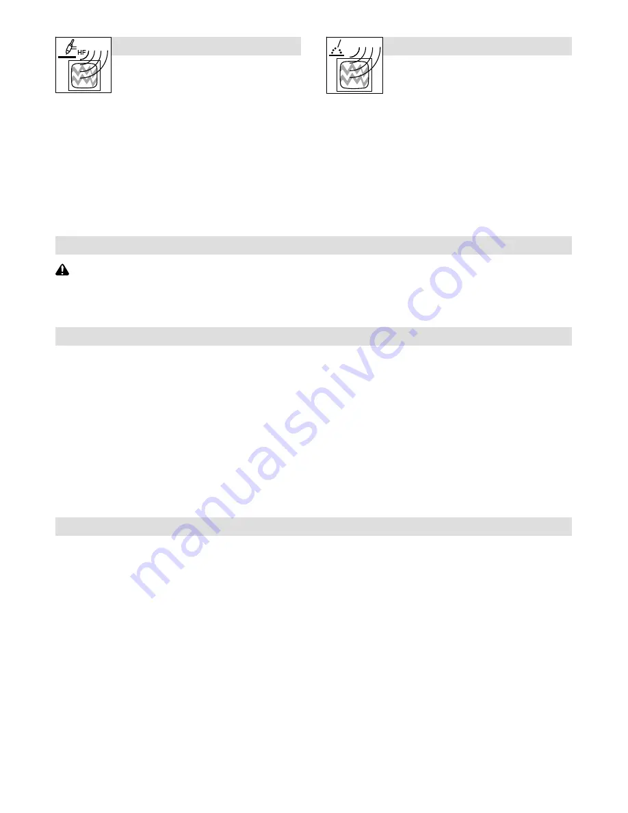
H.F. RADIATION can cause interference.

D

High-frequency (H.F.) can interfere with radio

navigation, safety services, computers, and

communications equipment.

D

Have only qualified persons familiar with electronic equipment

perform this installation.

D

The user is responsible for having a qualified electrician prompt-

ly correct any interference problem resulting from the installa-

tion.

D

If notified by the FCC about interference, stop using the

equipment at once.

D

Have the installation regularly checked and maintained.

D

Keep high-frequency source doors and panels tightly shut, keep

spark gaps at correct setting, and use grounding and shielding to

minimize the possibility of interference.

ARC WELDING can cause interference.

D

Electromagnetic energy can interfere with

sensitive electronic equipment such as

computers and computer-driven equipment

such as robots.

D

Be sure all equipment in the welding area is electromagnetically

compatible.

D

To reduce possible interference, keep weld cables as short as

possible, close together, and down low, such as on the floor.

D

Locate welding operation 100 meters from any sensitive elec-

tronic equipment.

D

Be sure this welding machine is installed and grounded

according to this manual.

D

If interference still occurs, the user must take extra measures

such as moving the welding machine, using shielded cables,

using line filters, or shielding the work area.

1-4. California Proposition 65 Warnings

WARNING: This product can expose you to chemicals in-

cluding lead, which are known to the state of California to

cause cancer and birth defects or other reproductive

harm.

For more information, go to www.P65Warnings.ca.gov.

1-5. Principal Safety Standards

Safety in Welding, Cutting, and Allied Processes,

 American Welding

Society standard ANSI Standard Z49.1. Website: www.aws.org.

Safe Practice For Occupational And Educational Eye And Face Protec-

tion,

 ANSI Standard Z87.1 from American National Standards Institute.

Website: www.ansi.org.

Safe Practices for the Preparation of Containers and Piping for Welding

and Cutting,

 American Welding Society Standard AWS F4.1 from Glob-

al Engineering Documents. Website: www.global.ihs.com.

Safe Practices for Welding and Cutting Containers that have Held Com-

bustibles,

 American Welding Society Standard AWS A6.0 from Global

Engineering Documents. Website: www.global.ihs.com.

National Electrical Code,

 NFPA Standard 70  from National Fire Protection

Association. Website: www.nfpa.org and www. sparky.org.

Safe Handling of Compressed Gases in Cylinders,

 CGA Pamphlet P-1

from Compressed Gas Association. Website:www.cganet.com.

Safety in Welding, Cutting, and Allied Processes,

 CSA Standard

W117.2 from Canadian Standards Association.

Website: www.csagroup.org.

Standard for Fire Prevention During Welding, Cutting, and Other Hot

Work,

 NFPA Standard 51B from National Fire Protection Association.

Website: www.nfpa.org.
OSHA

 Occupational Safety and Health Standards for General Industry

,

Title 29, Code of Federal Regulations (CFR), Part 1910.177 Subpart N, Part

1910 Subpart Q, and Part 1926, Subpart J. Website: www.osha.gov.
OSHA 

Important Note Regarding the ACGIH TLV, Policy Statement on

the Uses of TLVs and BEIs.

 Website: www.osha.gov.

Applications Manual for the Revised NIOSH Lifting Equation

 from


the

National Institute for Occupational Safety and Health (NIOSH).

Website: www.cdc.gov/NIOSH.

1-6. EMF Information

Electric current flowing through any conductor causes localized electric

and magnetic fields (EMF). The current from arc welding (and allied pro-

cesses including spot welding, gouging, plasma arc cutting, and

induction heating operations) creates an EMF field around the welding

circuit.  EMF fields can interfere with some medical implants, e.g. pace-

makers. Protective measures for persons wearing medical implants

have to be taken. For example, restrict access for passers

by or con-

duct individual risk assessment for welders. All welders should use the

following procedures in order to minimize exposure to EMF fields from

the welding circuit:

1. Keep cables close together by twisting or taping them, or using a

cable cover.

2. Do not place your body between welding cables. Arrange cables

to one side and away from the operator.

3. Do not coil or drape cables around your body.

4. Keep head and trunk as far away from the equipment in the

welding circuit as possible.

5. Connect work clamp to workpiece as close to the weld as

possible.

6. Do not work next to, sit or lean on the welding power source.

7. Do not weld whilst carrying the welding power source or wire

feeder.

About Implanted Medical Devices:

Implanted Medical Device wearers should consult their doctor and the

device manufacturer before performing or going near arc welding,  spot

welding, gouging, plasma arc cutting, or induction heating operations.

If cleared by your doctor, then following the above procedures is recom-

mended.

Summary of Contents for ST-24w

Page 1: ...Processes Description MIG GMAW Welding Flux Cored FCAW Welding Wire Feeder OM 287388B 2020 02 ST 24w And ST 24wD CE For product information Owner s Manual translations and more visit www MillerWelds com ...

Page 2: ...oducts Please take time to read the Safety Precautions They will help you protect yourself against potential hazards on the worksite We ve made installation and operation quick and easy With Miller you can count on years of reliable service with proper maintenance And if for some reason the unit needs repair there s a Troubleshooting section that will help you figure out what the problem is and ou...

Page 3: ... Environmental Specifications 8 SECTION 4 INSTALLATION 9 4 1 Selecting A Location 9 4 2 Equipment Connection Diagrams 10 4 3 14 Pin Receptacle Shielding Gas And Weld Cable Connection 10 4 4 14 Pin Receptacle Information 11 4 5 Connecting Welding Gun 11 4 6 Optional Meter Circuit Board Settings 12 4 7 Installing Wire Guide And Drive Roll 13 4 8 Installing And Threading Welding Wire 14 4 9 Installin...

Page 4: ......

Page 5: ...llow ing electrically hazardous conditions are present in damp locations or while wearing wet clothing on metal structures such as floors gratings or scaffolds when in cramped positions such as sitting kneeling or lying or when there is a high risk of unavoid able or accidental contact with the workpiece or ground For these conditions use the following equipment in order presented 1 a semiautomati...

Page 6: ...not possible tightly cover them with approved covers D Do not weld where flying sparks can strike flammable material D Protect yourself and others from flying sparks and hot metal D Be alert that welding sparks and hot materials from welding can easily go through small cracks and openings to adjacent areas D Watch for fire and keep a fire extinguisher nearby D Be aware that welding on a ceiling fl...

Page 7: ...to move unit be sure forks are long enough to extend beyond opposite side of unit D Keep equipment cables and cords away from moving vehicles when working from an aerial location D Follow the guidelines in the Applications Manual for the Revised NIOSH Lifting Equation Publication No 94 110 when manu ally lifting heavy parts or equipment OVERUSE can cause OVERHEATING D Allow cooling period follow r...

Page 8: ...cuments Website www global ihs com National Electrical Code NFPA Standard 70 from National Fire Protection Association Website www nfpa org and www sparky org Safe Handling of Compressed Gases in Cylinders CGA Pamphlet P 1 from Compressed Gas Association Website www cganet com Safety in Welding Cutting and Allied Processes CSA Standard W117 2 from Canadian Standards Association Website www csagrou...

Page 9: ...aint over cover the label Safe20 2017 04 Drive rolls can injure fingers Safe32 2012 05 Welding wire and drive parts are at welding voltage during operation keep hands and metal objects away Safe33 2017 04 Do not discard product where applicable with general waste Reuse or recycle Waste Electrical and Electronic Equipment WEEE by disposing at a designated collection facility Contact your local recy...

Page 10: ...rby and have a watchperson ready to use it Safe63 2012 06 Do not weld on drums or any closed containers Safe64 2017 04 10 Falling unit can cause injury Do not move or operate unit where it could tip Safe53 2017 04 Become trained and read the instructions before working on the machine or welding Safe65 2012 06 Wear hat and safety glasses Use ear protection and button shirt collar Use welding helmet...

Page 11: ...ored Arc Welding Gun FCAW On Off Alternating Current Circuit Breaker Gas Metal Arc Welding GMAW Gun Gas Input Voltage Input I2 Rated Current Wire Run In Speed V Volts Hz Hertz Trigger Hold On Trigger Hold Off Positive I1 Primary Current Water Coolant Output A Amperes IP Degree Of Protection Jog Purge Burnback Time U2 Load Voltage Water Coolant Input Notes ...

Page 12: ...ctromagnetic Fields EMF This equipment shall not be used by the general public as the EMF limits for the general public might be exceeded during welding This equipment is built in accordance with EN 60974 1 and is intended to be used only in an occupational environment where the general public access is prohibited or regulated in such a way as to be similar to occupational use by an expert or an i...

Page 13: ...its cylinder Wire feeder shown is repre sentative only and may not reflect actual unit 1 Wire Feeder 2 Rubber Feet Choose slot that allows all rubber feet to sit securely on top of welding power source 3 Wire Spool Reel 4 Gas Cylinder w Hose And Regulator Customer Supplied Shielding gas pressure not to exceed 100 psi 689 kPa 5 Welding Power Source 6 Running Gear 1 3 5 4 2 6 ...

Page 14: ...ams 115VAC Contactor 3 2 6 6 5 5 4 1 4 1 Gas Connections Shielding gas pressure not to exceed 0 500 Mpa 72 PSI 2 14 Pin Receptacle RC9 Use interconnecting cord to make connection to welding power source 3 Power Switch 4 Weld Cable Terminal 5 Weld Cable From Welding Power Source Push cable onto terminal and rotate 4 3 14 Pin Receptacle Shielding Gas And Weld Cable Connection 805 233 A 805 227 A Too...

Page 15: ...0 volts DC output to remote control with respect to pin D D Remote control circuit common E 0 to 10 volts DC input command signal from remote control with respect to pin D F Current feedback 0 to 10 volts DC 1 V 100 A H Voltage feedback 0 to 10 volts DC 1 V 10 arc volts The remaining pins are not used Ref S 0004 A 1 Gun Feeder Adapter 2 Gun Connector Insert gun connector into adapter Tighten locki...

Page 16: ...er 1 2 X Indicates switch position does not affect specified function Means switch must be in this position 2 1 Digital Amperage Display Hold Function ON Hold Function OFF 1 2 3 4 S2 1 2 3 4 Voltage Measurement 0 100V Current Signal 1 2 3 4 1 2 3 4 1 2 3 4 Step Voltage Power Source Signal Not Available Wire Feed Speed Display Inches Minute 1 2 3 4 1 2 3 4 1 2 3 4 Or 0 10V Electronic Control P Sour...

Page 17: ... possible without touching Tighten screw 3 Drive Roll The drive roll consists of two differ ent sized grooves The stamped markings on the end surface of the drive roll refers to the groove on the opposite side of the drive roll The groove closest to the motor shaft is the proper groove to thread 4 Drive Roll Securing Nut Turn nut one click to secure drive roll 5 Euro Adapter Securing Screw 1 4 in ...

Page 18: ...g Adjust tension nut so wire is taut when wire feed stops 3 Pressure Assembly Adjustment Knob Lay gun cable out straight A Open pressure assembly hold wire tightly and cut off end Push wire through guides int gun B Close and tighten pressure assembly Press Jog button until wire comes out gun C To adjust drive roll pressure press gun trigger to feed wire against wood surface Tighten knob so wire do...

Page 19: ... screw to remove spool hub from the spool support bracket Open the spool cover and place it on the spool support bracket Use round head screws to install spool cover Tighten nuts to secure Rein stall hub 4 9 Installing Optional Spool Cover 956142644_5 A 1 2 3 Notes ...

Page 20: ...tch Press Gas Purge Switch to ener gize gas valve to purge air from gun or adjust gas regulator 5 Trigger Hold Switch Push switch up to weld without holding gun trigger throughout the weld cycle To start weld cycle press and re lease gun trigger within three se conds after an arc has been struck To end weld press and release gun trigger Power switch is on rear panel see Section 4 3 6 Water Cooling...

Page 21: ...ol to set wire feed speed before arc is initiated 3 Wire Burn Back Control Use control to prevent wire elec trode from sticking in weld pool Close side door 1 2 3 SECTION 6 MAINTENANCE TROUBLESHOOTING Disconnect power before maintaining 6 1 Routine Maintenance n Check Clean l Replace Every 3 Months l Unreadable Labels Weld Terminals nl Weld Cable l Cracked Parts n 14 Pin Cord n Gas Hose and Fittin...

Page 22: ...ve roll see Parts List Clean or replace dirty or worn drive roll see Section 4 7 Remove weld spatter around nozzle opening Replace contact tip or liner See gun Owner s Manual Have Factory Authorized Service Agent check drive motor and control board PC1 Wire feeds when Jog switch is pressed but not when gun trigger is pressed Check gun trigger connection at wire feeder Check gun trigger leads and t...

Page 23: ...SECTION 7 ELECTRICAL DIAGRAM 210 937 A 956 142 625 On power source that support voltage feedback and have the meter option vfdbk mode connect PLG5 on RC1 Figure 7 1 Circuit Diagram For Wire Feeder With Optional Equipment ...

Page 24: ...SECTION 8 PARTS LIST 956 142 644 _3 B 1 2 3 4 5 6 7 8 9 10 11 12 13 14 15 16 17 18 19 20 21 22 23 24 25 26 27 28 29 30 31 32 33 34 35 36 37 38 39 40 41 42 43 44 45 46 47 48 49 50 51 52 15 Fig 8 2 Figure 8 1 Main Assembly ...

Page 25: ...n Off 1 1 28 056076192 Receptacle w Pins 1 1 29 056076216 Receptacle Twlk Insulated Male 1 1 30 R1 056059182 Potentiometer WFS 1 T 2W 1k Ohm 1 1 31 R2 056059182 Potentiometer WFS 1 T 2W 1k Ohm 1 1 32 117090005 Case Assembly 1 1 33 PC2 057084129 Circuit Card Assembly Digital Display 0 1 34 S4 056067260 Switch Rocker Spst On None On 4Va 28VDC 1 1 35 207075 Knob Pointer WFS 1 1 35 207075 Knob Pointer...

Page 26: ... Page 22 956 142 644_ 11 11 10 10 14 13 15 18 15 16 16 29 30 9 26 19 21 22 23 24 26 16 15 8 5 6 3 2 1 25 7 32 20 24 23 22 21 19 15 16 26 31 27 27 28 4 3 17 26 12 33 32 Figure 8 2 Drive Assembly Wire 4 Drive Roll ...

Page 27: ...oll w Component 24 Pitch 4 17 601872 Nut 1 18 156009124 Washer D5 x 15 x 1 2 1 19 010224 Pin Spring CS 187 x 1 000 2 20 230691 Lever Mounting Pressure Gear 1 21 225718 Fastener Pinned 2 22 198080 Cup Spring 2 23 196897 Spring CPRSN 695 Od x 095 Wire x 1 500 2 24 196895 Knob Tension 2 25 203562 Screw 1 26 166072 Spacer Gear 4 27 151828 Pin Cotter Hair 042 x 750 2 28 079634 Pin Hinge 1 29 156019804 ...

Page 28: ... V Grooved 156 193 056 207 1 0 mm 0 040 in 0 040 in 191 917 053 696 V Grooved 056 192 056 206 1 2 mm 0 045 in 0 045 in 046 782 053 697 V Grooved 056 193 056 207 1 6 mm 1 16 in 0 062 in 046 784 053 699 V Grooved 056 195 056 209 0 9 mm 0 035 in 0 035 in 044 750 072 000 U Grooved 056 192 056 206 1 2 mm 0 045 in 0 045 in 046 785 053 701 U Grooved 056 193 056 207 1 3 mm 0 052 in 0 052 in 046 786 053 70...

Page 29: ...Notes Work like a Pro Pros weld and cut safely Read the safety rules at the beginning of this manual ...

Page 30: ...Notes Work like a Pro Pros weld and cut safely Read the safety rules at the beginning of this manual ...

Page 31: ...asma Cutting Torches No Labor Induction Heating Power Sources Coolers NOTE Digital Recorders are Warranted Separately by the Manufacturer Load Banks Motor Driven Guns except Spoolmate Spoolguns PAPR Blower Unit No Labor Positioners and Controllers Racks For Housing Multiple Power Sources Running Gear Trailers Subarc Wire Drive Assemblies Supplied Air Respirator SAR Boxes and Panels TIG Torches No ...

Page 32: ...e Please complete and retain with your personal records Owner s Record Always provide Model Name and Serial Style Number Contact a DISTRIBUTOR or SERVICE AGENCY near you Welding Supplies and Consumables Options and Accessories Service and Repair Replacement Parts Owner s Manuals Contact the Delivering Carrier to For Service File a claim for loss or damage during shipment For assistance in filing o...

Reviews: