background image

OM-212296 Page 28

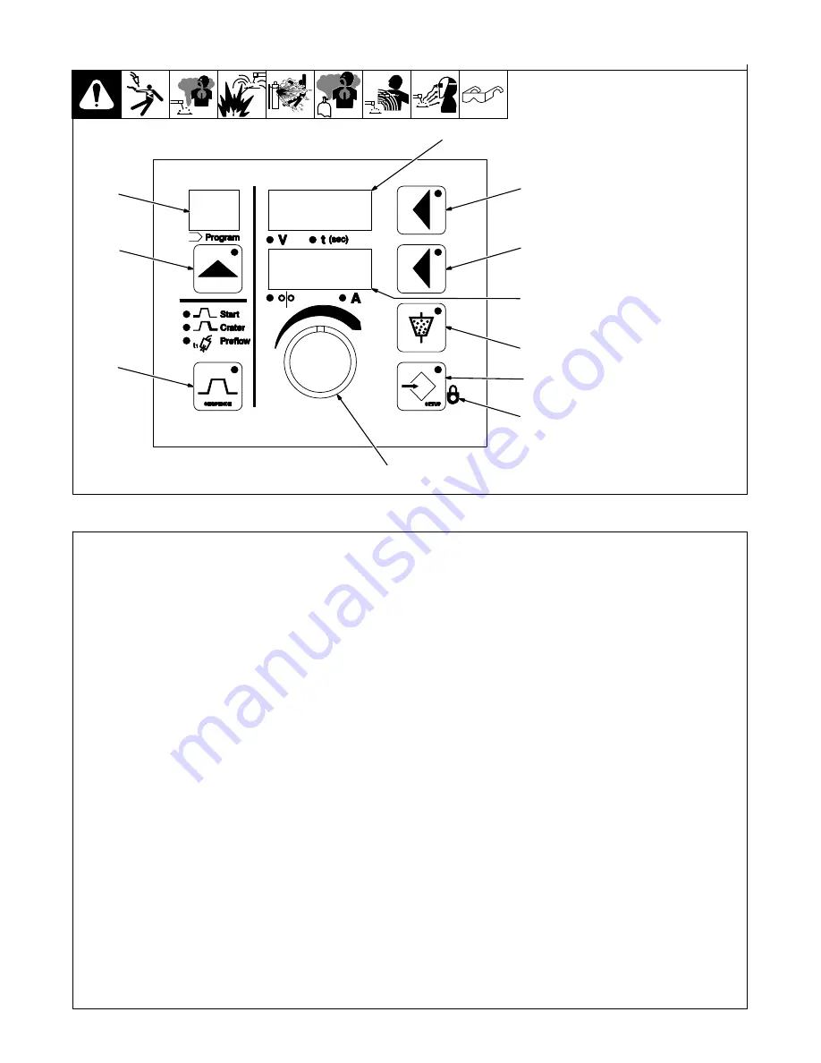
6-10. Auxiliary Menus

Ref. 236 564-B

1

Program Display

2

Program Push Button

3

Sequence Push Button

4

Upper Display

5

Upper Display Push Button

6

Lower Display

7

Lower Display Push Button

8

Adjust Control

9

Setup Push Button

10 Flux Push Button

11 Lock LED

1

2

3

4

5

7

6

10

9

8

11

Auxiliary Menus (Continued)

Auxiliary Menu

An auxiliary menu is provided when both
the Sequence and Setup buttons are
pressed simultaneously. The Setup and
Sequence button LEDs flash when in the
auxiliary menu. Press the Setup button to
scroll forward, or press the Sequence but-
ton to scroll backwards through the auxilia-
ry menu.

.

To exit auxiliary menu at any time,
press Sequence and Setup simulta-
neously, or press the inch up or inch
down button.

1

Code

Upon leaving the auxiliary menu, the user is
asked if a password code, indicated by
“CODE” in the top display, should be acti-
vated. By default, the code is off, indicated
by “OFF” in the lower display. The user may
enter a numerical password between 0 and
999 by turning the Adjust control. When the
user re-enters the auxiliary menu, the pass-
word code must be selected to gain access
to the auxiliary menu. A failed attempt re-
turns the user to the weld screen and a
counter will increment. The counter in the
program display shows the number of in-
correct attempts. The user has five at-
tempts to enter the correct password code
before being locked out of the auxiliary
menu, indicate by “LOCK”, in the lower dis-
play. After five failed attempts, the power
may be cycled to continue welding, but the
user will remained locked out of the auxilia-
ry menu. Pressing the Program, Sequence,
upper display, and Setup buttons simulta-

neously resets the counter to zero (0),as
shown in the weld screen. When the count-
er is reset,“CODE” is shown in the upper
display, and “RESET” in the lower display.
Pressing the Program, Sequence, upper
display, and Setup buttons simultaneously
again, will reset the unit to the factory de-
faults (see Section on Reset To Factory
Settings), 
indicated by “WIPE” in the upper
display. Resetting the unit will also turn off
the password code feature.

2

Power Source Selection

The upper display shows “PSS”. The lower
display shows “ON” or “OFF”. Use Adjust
control to select “ON” or “OFF”.

3

Voltage Range Lock

Voltage range lock is active when “LOCK”
is shown in the lower display and the Volts
LED is lit. The voltage range lock is off by
default, and is confirmed by “OFF” being
shown in the upper display. To set a voltage
variance between 0 to 10 volts from preset
voltage, press the upper display button and
rotate the Adjust control to the desired volt-
age. The voltage range lock is program de-
pendent, a different voltage variance may
be locked in for each program and indepen-
dent from the wire feed speed and amper-
age lock.

.

If locks are active, only those programs
with locks are accessible and the lock
LED will be on. To quickly enable or dis-
able the locks for all programs, press
the upper and lower display push but-
tons at the same time.

4

Amperage Range Lock

The amperage range lock is indicated by
“LOCK” in the upper display and a lit Amps
LED. The amperage range lock is set to off,
indicated by “OFF” in the lower display or
0.0 to 250 amperes. The amperage range
lock is program dependant and indepen-
dent for wire feed speed or voltage lock.

.

If locks are active, only those programs
with locks are accessible and the lock
LED will be on. To quickly enable or dis-
able the locks for all programs, press
the upper and lower display push but-
tons at the same time.

5

Wire Feed Speed Range Lock

The wire feed speed range lock is indicated
by “LOCK” in the upper display and a lit
Wire Speed LED. The wire feed speed
range lock is off by default, and “OFF” is
shown in the lower display. To set a wire
feed speed variance between 0 to 250 ipm
(0 to 6.3 mpm) from the preset wire feed
speed, press the lower display button and
turn the Adjust control until the desired wire
feed speed variance is set. The wire feed
speed range lock is program dependent, a
different wire feed speed variance may be
set for each program and independent of
from voltage and amperage locks.

.

If locks are active, only those programs
with locks are accessible and the lock
LED will be on. To quickly enable or dis-
able the locks for all programs, press
the upper and lower display push but-
tons at the same time.

Summary of Contents for HDC 1500DX

Page 1: ...escription OM 212 296Y 2016 06 28 Submerged SAW Welding Submerged Arc Controller For Automatic Welding HDC 1500DX File SUBMERGED SAW For product information Owner s Manual translations and more visit...

Page 2: ...ntinue the tradition They re just as committed to providing equipment and service that meets the high standards of quality and value established in 1929 This Owner s Manual is designed to help you get...

Page 3: ...mental Specifications 11 SECTION 5 INSTALLATION 12 5 1 Typical Equipment Location 12 5 2 Mounting Hole Layout 12 5 3 Typical Connection Diagram With Miller Power Sources 13 5 4 Left Side Panel Connect...

Page 4: ...M SELECT 31 SECTION 8 MOTOR TYPES 31 SECTION 9 SETTING SEQUENCE PARAMETERS 32 9 1 Sequence Parameters In A Program 32 SECTION 10 MAINTENANCE TROUBLESHOOTING 33 10 1 Routine Maintenance 33 10 2 Circuit...

Page 5: ...neeling or lying or when there is a high risk of unavoid able or accidental contact with the workpiece or ground For these conditions use the following equipment in order presented 1 a semiautomaticDC...

Page 6: ...ared according to AWS F4 1 and AWS A6 0 see Safety Standards D Do not weld where the atmosphere can contain flammable dust gas or liquid vapors such as gasoline D Connect work cable to the work as clo...

Page 7: ...S can injure D Keep away from moving parts such as fans D Keep all doors panels covers and guards closed and securely in place D Have only qualified persons remove doors panels covers or guards for ma...

Page 8: ...PA Standard 51B from National Fire Protection Association Quincy MA 02269 phone 1 800 344 3555 website www nfpa org OSHA Occupational Safety and Health Standards for General Indus try Title 29 Code of...

Page 9: ...s dans un environnement humideou si l on porte des v tements mouill s sur des structures m talliquestelles que sols grilles ou chafaudages en position coinc e comme assise genoux ou couch e ou s il y...

Page 10: ...br lures Le contact accidentel de l lectrode avec des objets m talliques peut provoquer des tincelles une explosion un sur chauffement ou un incendie Avant de commencer le soudage v rifier et s assur...

Page 11: ...areil D Tenir l quipement c bles et cordons distance des v hicules mobiles lors de toute op ration en hauteur D Suivre les consignes du Manuel des applications pour l quation de levage NIOSH r vis e P...

Page 12: ...ational Electrical Code NFPA Standard 70 from National Fire Protec tion Association Quincy MA 02269 phone 1 800 344 3555 website www nfpa org and www sparky org Safe Handling of Compressed Gases in Cy...

Page 13: ...ur local distributor for further information Safe37 2012 05 3 2 Symbols And Definitions Some symbols are found only on CE products A Amperage Remote Output Hz Hertz V Volts Start Time Input Single Pha...

Page 14: ...l Location The serial number and rating information for this product is located on the side Use rating label to determine input power requirements and or rated output For future reference write serial...

Page 15: ...o 104 F 10 to 40 C 4 to 131 F 20 to 55 C IP21 2014 06 B Information On Electromagnetic Compatibility EMC This Class A equipment is not intended for use in residential locations where the electrical po...

Page 16: ...Ref 131 138 A 1 Welding Power Source 2 Side Beam 3 Weld Control 4 Spool Support 5 Wire Drive Assembly 6 Automatic Welding Gun 1 2 6 3 4 5 5 2 Mounting Hole Layout Ref 803 021 B 8 in 203 mm 10 3 4 in 2...

Page 17: ...lding power source and weld control and disconnect input power before making connections Use remote voltage sense leads in all applications Suggested size remote voltage sense wire is 12 gauge or high...

Page 18: ...nal terminal blocks 4 4 Pin Receptacle Connection To Flux Hopper Shielding Gas Valve 5 14 Pin Receptacle Connection To Welding Power Source 6 10 Pin Receptacle Connection to Wire Drive Motor To connec...

Page 19: ...lock TB2 3 Terminal Block TB1 4 Securing Screw Terminal Block 5 Stripped Lead 6 Typical Lead Being Connected To Terminal Block 7 Access Hole Used For Connections To Terminal Blocks Flux Valve etc Inst...

Page 20: ...Remote Jog Down When connected to remote common jogs wire down Remote Common Circuit common for remote capabilities 5 7 Terminal Block TB2 Connection Information Terminals Function Information Red 115...

Page 21: ...inal Block TB2 3 Access Hole Used For Connections To Terminal Blocks Flux Valve etc Install strain relief customer supplied in access hole Strip 1 4 in 6 mm insulation off end of leads Insert four con...

Page 22: ...power source present whenever power source is On B B Normally open set of relay contacts connect A to B when Start is pressed and preflux timer has timed out Remote Output Control C C Remote command...

Page 23: ...a TB2 Terminal Socket Information Flux Hopper Hookups A Red 115 volts AC to power flux hopper B Black Switched 115 volts AC to power flux hopper C White Circuit common for 115 volts AC for flux hopper...

Page 24: ...nse leads are out of the current paths Sense leads detect arc voltage ac curately Best starts arcs and most reliable results BAD Sense lead is affected by weld current Due to voltage drops across work...

Page 25: ...rops across work piece arc voltage may be low causing need for deviation from standard procedures BAD Current flow from lead affects trail sense Current flow from trail affects lead sense Neither sens...

Page 26: ...age accurately No voltage drop between lead and trail sense Best starts arcs and most reliable results Work Clamp Trail Lead Trail Lead 5 13 Remote Voltage Sense Leads Placement Guidelines For Multipl...

Page 27: ...a power source selection the operator may press the Program Button to avoid having to wait the five seconds When turning off the controller the selected power source will be retained Next Time Contro...

Page 28: ...cycle 6 1 Power Switch And Buttons 803 448 A 1 Power Switch 2 Start Button 3 Stop Button 4 Inch Up Button 5 Inch Down Button 2 3 1 5 4 6 2 Program Push Buttons 1 Program Display The number of the acti...

Page 29: ...The upper display push button LED illumi nates to indicate that information displayed can be changed with the Adjust control 4 Volts LED 5 Time LED The LED s below the display illuminate to in dicate...

Page 30: ...ive The Adjust control can be used to change the setting from AUTO to a run in wire speed setting If a start condi tion is set run in is a percentage of the start wire speed otherwise run in is a perc...

Page 31: ...nce push button flashes and the Start LEDs flash In this condition the unit is in the Start sequence display mode and Start se quence parameters are shown in the dis plays When the Sequence push butto...

Page 32: ...lso turn off the password code feature 2 Power Source Selection The upper display shows PSS The lower display shows ON or OFF Use Adjust control to select ON or OFF 3 Voltage Range Lock Voltage range...

Page 33: ...SB1 will engage when the start button is pressed and preflux has timed out When a positive time is selected SB1 will engage when the selected time has elapsed after an arc is es tablished When a nega...

Page 34: ...the gas flow function and CV C mode is not available The Flux button now controls the gas flow Refer to section 6 9 for op erating instructions 6 12 Operation Of HDC In GMAW MIG Mode 1 4 Ref 803 449...

Page 35: ...ollowing table Program Selected RC24 Pin 1 to Pin 2 RC26 Pin 1 to Pin 2 Program 1 Not Connected Not Connected Program 2 Not Connected Connected Program 3 Connected Not Connected Program 4 Connected Co...

Page 36: ...et to zero in any timed se quence except Weld the sequence is skipped Sequence Parameters Volts CV or CV C Amps CV C Wirespeed CV Seconds 1 Preflow 2 Run In 3 Start 4 Weld 5 Crater 6 Burnback 7 Postfl...

Page 37: ...14 pin cord Check gas hose and fittings Check gun cable Replace cracked parts 6 Months Blow out or vacuum inside During heavy service clean monthly OR Clean drive rolls 10 2 Circuit Breaker CB1 Turn...

Page 38: ...amps for the unit to go from run in to weld parameters Have Factory Authorized Service Agent check control board PC1 and replace if necessary No contactor control for welding power source ensure that...

Page 39: ...any grounded equipment Turn the unit off for 10 seconds to clear the error message Separate welding cables from control cables Noise is creating an excessive amount of current in the safety ground Un...

Page 40: ...OM 212296 Page 36 SECTION 11 ELECTRICAL DIAGRAM 238 416 A Figure 11 1 Circuit Diagram...

Page 41: ...011 611 Switch Tgl Dpdt 15A 1 9 236 564 Overlay Front Panel CE 1 10 238 273 Circuit Card Assy Switches 1 11 250 508 Circuit Card Assy Display Micro W Program 1 12 221 404 XFMR Control 30Va 24V 24V 18...

Page 42: ...h 1 236 767 Label CB1 1 236 565 Label Warning Electric Shock Power Still Present 1 236 569 Label Rating Card CSA CE 300438 1 236 226 Label Remote Connections 1 212 591 Cable Motor 10 Ft 10 Pin 1 178 8...

Page 43: ...ns and Subarc SAW Torches Remote Controls and RFCS RJ45 Replacement Parts No labor Roughneck Guns Spoolmate Spoolguns Miller s True Blue Limited Warranty shall not apply to 1 Consumable components suc...

Page 44: ...your personal records Always provide Model Name and Serial Style Number Contact a DISTRIBUTOR or SERVICE AGENCY near you Welding Supplies and Consumables Options and Accessories Personal Safety Equip...

Reviews: