General
OM-244 814 Page 45
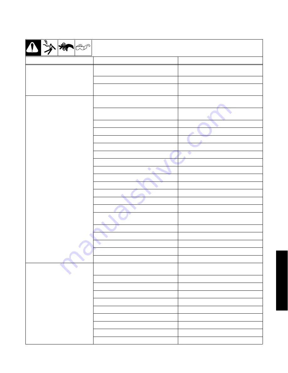
9-9. Basic Welding Troubleshooting
Listed below are some problems, causes and remedies related to welding operations; however, this list does not contain every possible condition that
could be encountered in welding.
Trouble
Probable Cause
Remedy
No weld output; unit completely
inoperative
Line disconnect switch in Off position
Place switch in On position
Power source switch in Off position
Place switch in On position
Primary power fuse blown or circuit breaker tripped Replace fuse or reset circuit breaker and check in-
put voltage
Weld output is present, but wire stops
feeding while welding
Wire feeder protective fuse blown or circuit breaker
tripped
Replace fuse or reset circuit breaker and find over-
load condition
No start input signal to weld control
Check external start, PLC, or robot signal to weld
control
Wire feeder drive rolls misaligned
Align drive rolls
Wrong size drive rolls
Replace with proper size drive rolls
Too much or too little drive roll pressure
Adjust drive roll pressure
Too much tension set at wire spool
Reduce wire spool tension
Restriction in unspooler or drum adapter
Replace unspooler or repair restriction
Feeder motor burnt out
Test motor and replace if necessary
Gun liner dirty or restricted
Remove gun liner and clean or replace
Wrong type or size of liner
Install proper size liner
Broken or damaged gun or torch
Replace faulty parts
Contact tip opening restricted
Replace contact tip
Wrong size or type of contact tip
Replace with proper size and type contact tip
Sharp bends or kinks in gun cable or liner
Straighten gun cable and/or replace liner
Inlet cable too long
Reduce distance to shorten inlet cable or use an in-
termediate drive
Gun overheating
Use gun with proper amperage rating
Wrong size wire
Match wire size to liner and contact tip
Guides rubbing on drive rolls
Adjust or position guides properly
Drive rolls jammed
Remove foreign object from gears
Motor cable disconnected or damaged
Connect, repair or replace motor cable
Porosity in weld
Dirty base metal, heavy oxides, mill scale, oil, etc Clean base metal by brushing, grinding or use
chemical cleansing before welding
Regulator/flowmeter faulty
Adjust or replace regulator/flowmeter
Gas cylinder valve closed
Open gas cylinder valve
Gas regulator diaphragm defective
Replace regulator
Flowmeter cracked or broken
Repair or replace flowmeter
Gas hose disconnected or leaking
Connect or replace gas hose
Too much or too little gas flow
Adjust for proper gas flow
Moisture in shielding gas
Replace gas cylinder or supply
Wrong gas for wire type or transfer mode
Use correct shielding gas
Feeder gas solenoid faulty
Replace solenoid
Summary of Contents for Axcess E 300
Page 14: ...OM 244 814 Page 10 ...
Page 18: ...OM 244 814 Page 14 Notes ...
Page 22: ...OM 244 814 Page 18 Notes ...
Page 26: ...OM 244 814 Page 22 Notes ...
Page 30: ...OM 244 814 Page 26 Notes ...
Page 56: ...OM 244 814 Page 52 Notes ...
Page 63: ...Trouble OM 244 814 Page 59 Notes ...
Page 68: ...OM 244 814 Page 64 Figure 14 2 Circuit Diagram For Axcess E 300 2 Of 2 ...
Page 69: ...Circuits OM 244 814 Page 65 248 763 E Part 2 Of 2 ...
Page 70: ...OM 244 814 Page 66 Figure 14 3 Circuit Diagram For Axcess E 450 1 Of 2 ...
Page 71: ...Circuits OM 244 814 Page 67 245 131 F Part 1 Of 2 ...
Page 72: ...OM 244 814 Page 68 Figure 14 4 Circuit Diagram For Axcess E 450 2 Of 2 ...
Page 73: ...Circuits OM 244 814 Page 69 245 131 F Part 2 Of 2 ...
Page 74: ...OM 244 814 Page 70 Figure 14 5 Circuit Diagram For Axcess E 675 1 Of 2 ...
Page 75: ...Circuits OM 244 814 Page 71 250 570 C Part 1 Of 2 ...
Page 76: ...OM 244 814 Page 72 Figure 14 6 Circuit Diagram For Axcess E 675 2 Of 2 ...
Page 77: ...Circuits OM 244 814 Page 73 250 570 C Part 2 Of 2 ...
Page 78: ...OM 244 814 Page 74 Figure 14 7 Circuit Diagram For Axcess E Module ...
Page 79: ...Circuits OM 244 814 Page 75 250 571 C ...
Page 80: ...OM 244 814 Page 76 Notes ...
Page 106: ...Notes ...


