2
3
ver. 1.00
WiFi2 click manual
0100000070277
click
™
BOARD
www.mikroe.com
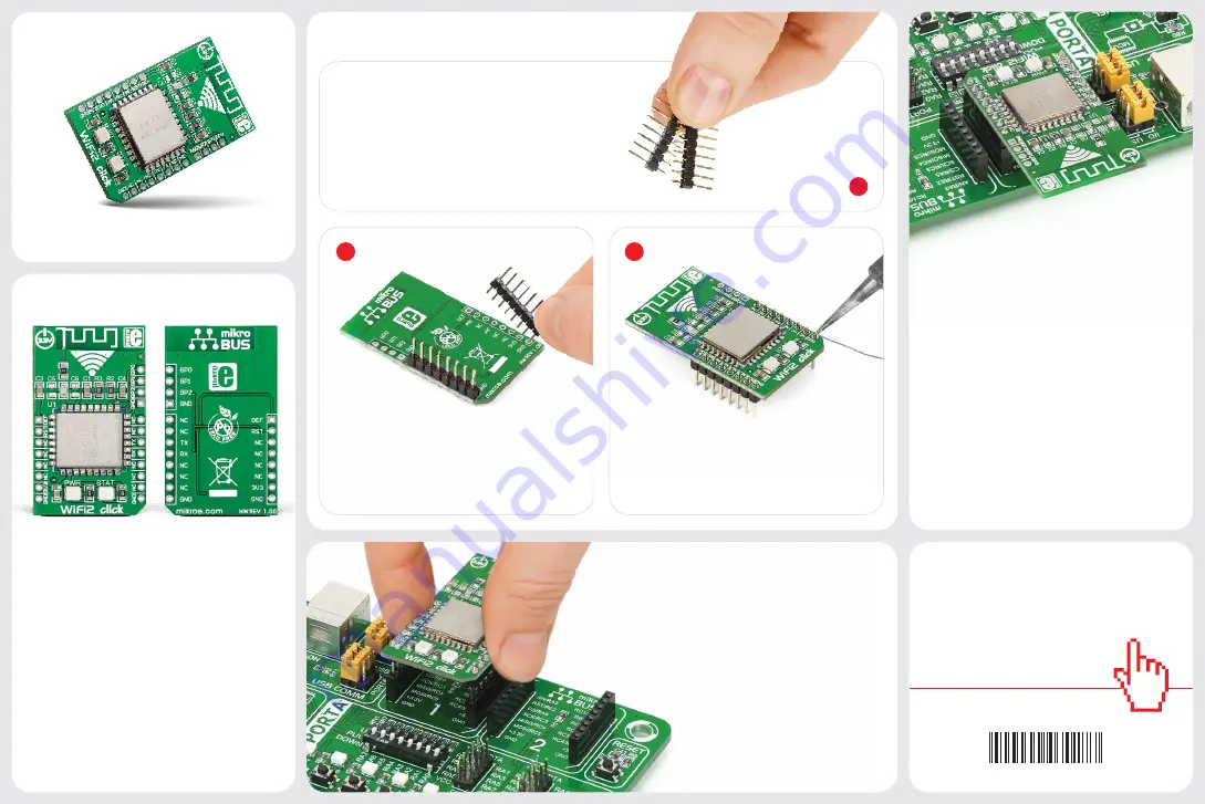
2. Soldering the headers
1. Introduction
3. Plugging the board in
Once you have soldered the headers your
board is ready to be placed into the desired
mikroBUS
™
socket. Make sure to align the
cut in the lower-right part of the board with
the markings on the silkscreen at the
mikroBUS
™
socket. If all the pins
are aligned correctly, push the
board all the way into the socket.
Turn the board upward again. Make sure
to align the headers so that they are
perpendicular to the board, then solder
the pins carefully.
Turn the board upside down so that
the bottom side is facing you upwards.
Place shorter pins of the header into the
appropriate soldering pads.
Before using your click
™
board, make sure
to solder 1x8 male headers to both left
and right side of the board. Two 1x8 male
headers are included with the board in
the package.
4. Essential features
WiFi2 click
™
can be set up both as a TCP/IP
client or server. You can configure it with
either a static or dynamic IP address. Use the
mikroBUS
™
AN line (DEF on this click) to reset
WiFi2 to default factory settings if needed.
WiFi2 click
™
supports standard security
authentication systems (WEP64/WEP128/
TKIP/ AES, WEP/WPA-PSK/WPA2-PSK); as
well as multiple network protocols (TCP/UDP/
DHCP/DNS). All these features make WiFi2
click ideal for home automation applications,
remote controls, telemetry and so on.
1
WiFi2 click
™
is an affordable solution for
adding WiFi functionality to your design.
The board carries the HLK-M30 WiFi
module, based on the universal serial
interface network standard, with a built-in
TCP/IP protocol stack. WiFi2 click
™
is
simple to use and is especially convenient
for IoT applications. It communicates with
the target board microcontroller through
mikroBUS
™
UART (TX, RX) RST, and AN
lines. It uses a 3.3V power supply.
WiFi2
click
™


