2
3
ver. 1.00
IR eclipse click
™
manual
0 100000 027301
click
™
BOARD
www.mikroe.com
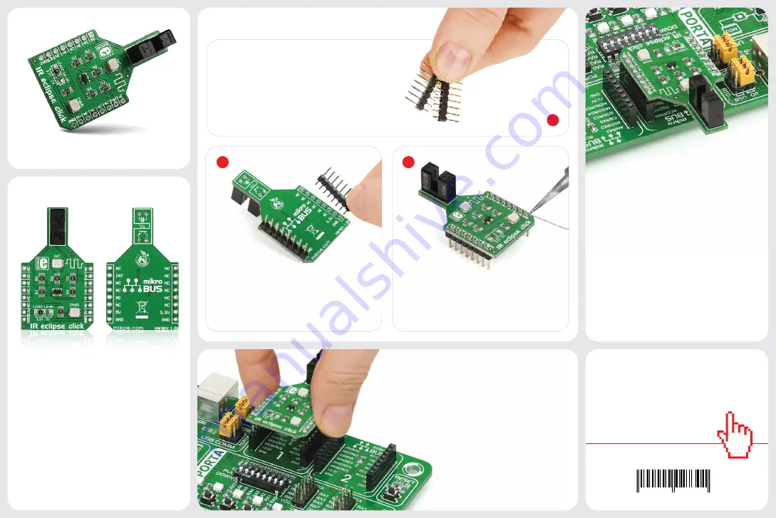
2. Soldering the headers
1. Introduction
3. Plugging the board in
Once you have soldered the headers your
board is ready to be placed into the desired
mikroBUS
™
socket. Make sure to align the
cut in the lower-right part of the board with
the markings on the silkscreen at the
mikroBUS
™
socket. If all the pins
are aligned correctly, push the
board all the way into the socket.
Turn the board upward again. Make sure
to align the headers so that they are
perpendicular to the board, then solder
the pins carefully.
Turn the board upside down so that
the bottom side is facing you upwards.
Place shorter pins of the header into the
appropriate soldering pads.
Before using your click
™
board, make sure
to solder 1x8 male headers to both left
and right side of the board. Two 1x8 male
headers are included with the board in
the package.
4. Essential features
Photo interrupter sensors are typically
used in printers, copiers, vending machines,
for optical limit switches and so on. You
can implement IR eclipse in your design
wherever there’s a need to detect the
position of a moving part, whether you need
to detect if said part is in correct place, or to
infer speed of rotation — as long as its thin
enough to fit in the 3mm-wide slit where
the infrared beam passes through.
1
IR eclipse
click
™
IR eclipse click
™
carries an
EE-SX198
photo
interrupter sensor. This sensor consists of
an infrared transmitter and receiver facing
each other and spaced apart by a 3mm
slit. When the beam from the transmitter
is eclipsed with by placing an object in the
gap (like a piece of paper), the sensor is
activated (indicated by the onboard INT
LED). IR eclipse click
™
communicates with
the target board through the
mikroBUS
™
INT line. It’s designed to work with either
a 3.3V or 5V power supply.


