

2
3
ver. 1.00
ccRF2 click
™
manual
0 100000 027554
click
™
BOARD
www.mikroe.com
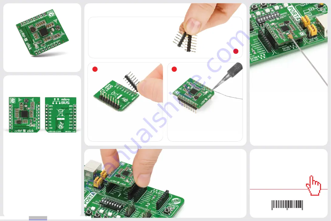
2. Soldering the headers
1. Introduction
3. Plugging the board in
Once you have soldered the headers your
board is ready to be placed into the desired
mikroBUS
™
socket. Make sure to align the
cut in the lower-right part of the board with
the markings on the silkscreen at the
mikroBUS
™
socket. If all the pins
are aligned correctly, push the
board all the way into the socket.
Turn the board upward again. Make sure
to align the headers so that they are
perpendicular to the board, then solder
the pins carefully.
Turn the board upside down so that
the bottom side is facing you upwards.
Place shorter pins of the header into the
appropriate soldering pads.
Before using your click
™
board, make sure
to solder 1x8 male headers to both left
and right side of the board. Two 1x8 male
headers are included with the board in
the package.
4. Essential features
The CC1120 IC on ccRF2 click
™
provides
extensive hardware support for packet
handling, data buffering, burst transmissions,
clear channel assessment, link quality
indication, and Wake-On-Radio. CC1120 also
integrates all filters, which removes the need
for costly external SAW and IF filters. It’s a
great solution for wireless communications
in home and building automation as well as
industrial monitoring and control.
1
ccRF2
click
™
ccRF2 click
™
will enable you to add a high
performance, low power consumption
single-chip radio transceiver to your design.
It carries CC1120, the fully integrated
radio transceiver designed mainly the
ISM (Industrial, Scientific, and Medical)
and SRD (Short Range Device) frequency
bands at 164–192 MHz, 274–320 MHz,
410–480 MHz, and 820–960 MHz. ccRF2
click
™
communicates with the target board
through
mikroBUS
™
SPI (MISO, MOSI, CSK),
and AN, RST, CS, PWM and INT lines. The
board uses a 3.3V power supply only.
Downloaded from