background image

Correct use

~

The appliance gets hot when in use

and remains hot for quite a while after
being switched off. Do not touch it
whilst it could still be hot.

~

When using a rangehood over the

cooktop, ensure that the burner is
always covered with a pan when in use.
Otherwise flames could be drawn up by
the suction of the rangehood, parts of
which could then be damaged or even
set on fire.

~

Do not leave the cooktop

unattended whilst it is being used.
Boiling fat or oil could ignite and cause
a fire.

~

If oil or fat does catch fire, do not

attempt to put out the flames with water.
Use a suitable fire blanket, saucepan
lid, damp towel or similar to smother the
flames.

~

Do not use the cooktop to heat up

the room. Due to the high temperatures
radiated, objects near the appliance
could catch fire. The life of the
appliance could also be reduced.

~

For added protection, it is advisable

to use heat-resistant pot holders or
gloves when using the appliance.
Ensure that they do not come into
contact with the flames. Do not use
large cloths, tea towels or similar as the
ends could touch the flames and catch
fire.
Take care not to let these items get
damp or wet as this causes heat to
transfer through the material more
quickly with the risk of scalding or
burning yourself.

~

Do not flambé under a rangehood.

The flames could set the rangehood on
fire.

~

Do not use the appliance as a

resting place for anything else. The
article could melt or catch fire if
residual heat is still present or if the
appliance is switched on by mistake.

~

Do not cover the appliance, e.g.

with a cloth, kitchen foil, etc. If the
cooktop is switched on inadvertently or
there is residual heat present, there is
the danger of the items catching fire.

~

Do not use plastic or aluminium foil

containers. These melt at high
temperatures, and could catch fire.

~

Do not heat up unopened tins of

food on the cooktop as pressure will
build up in the tin, causing it to
explode. This could result in injury and
scalding or damage.

~

Make sure all the components of the

gas burners have been correctly
assembled before switching on.

Warning and safety instructions

13

Summary of Contents for KM 2256

Page 1: ...instructions Gas cooktops KM 2256 KM 2257 KM 2257 1 To avoid the risk of accidents or damage to the appliance it is essential to read these instructions before it is installed and used for the first time M Nr 07 012 921 en AU NZ ...

Page 2: ...used in countries other than those specified on the appliance It is however set up for connection to the gas and electricity supplies in the countries specified For use in other countries please contact Miele in your country 2 ...

Page 3: ...Rapid ignition system 18 Controls 18 Switching on 19 Regulating the flame 20 Pans 21 Wok ring 22 Combi insert 22 Energy saving tips 23 Safety features 24 Thermoelectric safety ignition 24 Safety switch off 24 Cleaning and care 25 General notes 25 Stainless steel surfaces 26 Pan support control knob 26 Burners 27 Problem solving guide 30 Optional accessories 31 Contents 3 ...

Page 4: ...ng in dimensions 38 Installation 40 KM 2257 1 42 Appliance and building in dimensions 42 Installation 44 Securing the appliance 46 After installation 46 Electrical connection 47 Gas connection 48 Burner ratings 50 Conversion to another type of gas 51 Jet table 51 To change the main jets 52 To change the small jets 56 After changing the jets 57 After sales service data plate 58 Contents 4 ...

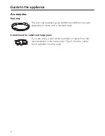
Page 5: ... 1 aSimmer burner bExtra high speed burner cDual Wok dHigh speed burner eStandard burner fPan support in three sections gCombi insert hWok ring Controls iFront left jBack left kMiddle lBack right mFront right Guide to the appliance 5 ...

Page 6: ...mponents The proper functioning of the burner can only be guaranteed if the burner components are positioned correctly The lobe a on the burner cap must fit into the recess b of the burner head The pin c on the burner head must fit into the recess d of the burner base The burner components cannot be twisted if they are in the correct position Guide to the appliance 6 ...

Page 7: ...Simmer standard high speed and extra high speed burners nBurner cap rBurner head sIgnition safety device tIgnitor uBurner base Guide to the appliance 7 ...

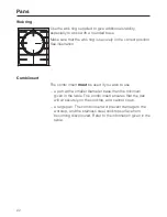
Page 8: ...tability to the wok especially to those with a rounded base Combi insert for small and large pans If you are using a pan which is smaller or larger than that recommended in the table under Pans then the combi insert supplied must be used Guide to the appliance 8 ...

Page 9: ...kfasts and other typical living quarters This does not include common shared facilities or commercial facilities within hotels motels or bed breakfasts This appliance must only be used to cook food and keep it warm Any other usage is at the owner s risk and could be dangerous Miele cannot be held liable for damage resulting from incorrect or improper use or operation This appliance is not intended...

Page 10: ...nce at all times Do not store anything which might arouse a child s interest in storage areas above or next to the appliance Otherwise they could be tempted into climbing onto the appliance with the risk of burning themselves Danger of burning Keep all pans out of reach of children Turn pan handles inwards away from the edge of the cooktop Danger of burning or scalding Special ooktop guards are av...

Page 11: ...doubt The connection to the gas supply must be carried out by a suitably qualified and competent person in strict accordance with current local and national safety regulations e g a qualified gas fitter If the appliance is supplied without a plug or if the plug is removed it must be connected to the mains electricity supply by a suitably qualified and competent electrician in strict accordance wit...

Page 12: ...ts are used If the connection cable is damaged it must be replaced by a suitably qualified electrician with a specialist connection cable of type H 05 VV F pvc insulated available from Miele Do not connect the appliance to the mains electricity supply by a multi socket unit or an extension lead These do not guarantee the required safety of the appliance e g danger of overheating This appliance is ...

Page 13: ...at they do not come into contact with the flames Do not use large cloths tea towels or similar as the ends could touch the flames and catch fire Take care not to let these items get damp or wet as this causes heat to transfer through the material more quickly with the risk of scalding or burning yourself Do not flambé under a rangehood The flames could set the rangehood on fire Do not use the appl...

Page 14: ...orage drawer or near this appliance Remove splashes of fat and other food debris from the surface as soon as possible These are a fire hazard Replace the pan supports carefully to avoid scratching the surface of the gas cooktop Using the gas cooktop will cause a build up of heat and moisture in the room in which it is installed Ensure that the room has sufficient natural or mechanical means of ven...

Page 15: ...n the door is open Close the furniture door only once the appliance has been switched off and the residual heat indicators have gone out If the appliance has not been used for a long period of time it should be thoroughly cleaned before it is used again It is also advisable to have the appliance tested by a qualified person for safety Miele cannot be held liable for damage caused by non compliance...

Page 16: ...erials which if handled or disposed of incorrectly could be potentially hazardous to human health and to the environment They are however essential for the correct functioning of your appliance or machine Therefore please do not dispose of your old machine or appliance with your household waste Please dispose of it at your local community waste collection recycling centre and ensure that it presen...

Page 17: ...ater and a small amount of washing up liquid applied with a soft sponge Dry all parts thoroughly after cleaning and then reassemble the burners see Cleaning and care Burners Clean the stainless steel trough with a damp cloth and then wipe dry Metal components have a protective coating which may give off a slight smell when heated up for the first time The smell and any vapours will dissipate after...

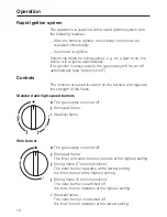
Page 18: ...sed to switch on the burners and regulate the strength of the flame Standard and high speed burners ß The gas supply is turned off Strongest flame Weakest flame Wok burner ß The gas supply is turned off Strongest flame The inner and outer burners operate at the highest setting Strong flame 7 o clock position The outer burner operates at the lowest setting the inner burner at the highest setting St...

Page 19: ...urner does not ignite turn the control to ß Ensure that the room is well ventilated and wait at least 1 minute before trying to light the cooktop again If the burner does not ignite the second time turn the control to ß and see Problem solving guide When switching on re ignition sometimes occurs 1 2 clicks if the flame on the thermal element goes out briefly or if the thermal element is not hot en...

Page 20: ...e control beyond the 6 o clock position To move from the high to the low setting you need to press in the control to pass the 6 o clock position To move from the high to the low setting turn the control anti clockwise until it stops Then press the control in continue to turn it anti clockwise past the obstruction and release it You can now select the setting you require To move from the low to the...

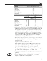
Page 21: ... the worktop wall claddings or surrounding units and also parts of the cooktop The manufacturer cannot be held liable for this type of damage Remember when purchasing new pans that manufacturers usually refer to the diameter at the top of the pan in their documentation Any heat resistant pans can be used Pans with thick bases are preferable as these distribute heat more evenly With thin bases ther...

Page 22: ...ert The combi insert must be used if you wish to use a pan with a smaller diameter base than the minimum given in the table The combi insert ensures that the pan will sit securely on the cooktop and cannot tip up a large pan The combi insert will prevent damage to the worktop and the stainless steel cooktop surface from becoming discoloured Refer to the information given in the table Pans 22 ...

Page 23: ...little water as possible Cooking times are greatly reduced when using a pressure cooker Turn the flame down promptly to a lower setting when the pan has come to the boil Wide shallow pans are preferable to tall narrow ones They will heat up faster Energy saving tips 23 ...

Page 24: ...le if food has boiled over or if there is a sudden draught To use the burner again turn the control clockwise to the ß position and switch on as normal Safety switch off If a burner is used for an unusually long period approx 4 hours it will switch off automatically To use the burner again turn the control clockwise to the ß position and switch on as normal Safety features 24 ...

Page 25: ... and the stainless steel cooktop Remove any soiling immediately To avoid damaging the outer surfaces of your appliance do not use cleaning agents containing soda alkalines ammonia acids or chlorides cleaning agents containing descaling agents stain or rust removers abrasive cleaning agents e g powder cleaners and cream cleaners solvent based cleaning agents dishwasher cleaner grill and oven cleane...

Page 26: ...elp keep your appliance looking good and to hinder resoiling see Optional accessories Apply sparingly with a soft cloth following the instructions on the packaging Printed surfaces Flame symbols The printing can be damaged if soiling e g food or fluids that contained salt olive oil is not removed immediately Remove any soiling immediately Do not use any stainless steel cleaner on printed surfaces ...

Page 27: ...d clean with a damp cloth only The ignitor and ignition safety device should be very carefully wiped clean using a well wrung out cloth Do not let the ignitor get wet If it gets wet it will not spark After cleaning dry all surfaces with a clean cloth Make sure that the flame slits are clean and completely dry The surface of the burner parts will become more matt with time This is quite normal and ...

Page 28: ...tion safety device s and the ignitor t extend through the respective burner head holes Finally position the burner cap n ensuring that the locating tabs fit into the notches in the burner head Important Please ensure that the components are placed in the correct order after cleaning is complete Cleaning and care 28 ...

Page 29: ... on the burner cap must fit into the recess b of the burner head The pin c on the burner head must fit into the recess d of the burner base Position the burner ring q over the burner head r Position the outer burner cover p onto the burner head r ensuring that all locating tabs are in the correct position Finally position the inner burner cover o into position Cleaning and care 29 ...

Page 30: ...ly the gas flame goes out after being lit During the ignition process the flames need to touch the ignition device so that it heats up If the flames do not touch the ignition device check that the burner cover is correctly in position there is no soiling on the ignition device Remove this carefully see Cleaning and care the ignitor on the burner does not spark Check whether the mains fuse has trip...

Page 31: ...er Original Miele ceramic and stainless steel cooktop cleaner 250 ml Removes heavy soiling limescale deposits and light discolouration Original Miele stainless steel conditioning agent 250 ml Removes water marks flecks and finger prints Helps keep the cooktop looking good for longer Original Miele all purpose microfibre cloth Removes finger marks and light soiling Optional accessories 31 ...

Page 32: ... the fat in the fryer It is essential to maintain a distance of at least 300 mm between these two appliances A gas cooktop may not be built in over a fridge fridge freezer freezer dishwasher washing machine or tumble dryer Ensure that the gas pipe and electrical cable are installed in such a way that they do not touch any parts of the appliance which become hot This could cause damage The electric...

Page 33: ...m above the burner cap must be maintained between them and the cooktop below When two or more appliances are installed together below a rangehood e g a gas cooktop and an induction cooktop combiset which have different safety clearances given in the installation instructions you should select the greater clearance of the two Side rear clearances to the cooktop Ideally the cooktop should be install...

Page 34: ...s burner AS 5601 non combustible surface or splashback shall be a 50 mm horizontal distance from the rear edge of the cooktop If the clearance between the periphery of any gas burner and the side wall is less than 300 mm the rear wall is less than 200 mm the walls must be protected with a non combustible material The protection must be extended a minimum distance of 150 mm above the burner refer g...

Page 35: ... and building in dimensions aFront bBuilding in depth cGas connection R 1 2 ISO 7 1 dElectrical connection eElectronics housing 100 x 200 mm Max building in depth including electronics housing 134 mm KM 2256 35 ...

Page 36: ...connection cable down through the cut out Place the cooktop in the cut out without securing it If the seals on the corners of the frame are not flush with the worktop surface the corner radius ß R4 can be carefully scribed to fit Connect the cooktop to the mains see Electrical connection Connect the appliance to the gas supply see Gas connection Secure the appliance at the back and front using the...

Page 37: ...nd possibly result in damage to the appliance or the worktop Tiled worktop Grout lines a and the hatched area underneath the appliance frame must be smooth and even If they are not the appliance will not sit flush with the worktop and the sealing strip underneath the appliance will not provide a good seal between the appliance and the worktop Tiled worktops must be a minimum of 5 mm thick to ensur...

Page 38: ...ISO 7 1 dElectrical connection eElectronics housing 100 x 200 mm Max building in depth including electronics housing 139 mm fStepped cut out for granite or marble worktops Please take careful note of the inset diagram for the cut out dimensions for granite or marble worktops KM 2257 38 ...

Page 39: ...e of the cooktop is accessible after installation and that the casing can be easily removed for maintenance If the underside of the cooktop is not freely accessible after installation the silicone sealant must be removed to enable the cooktop to be lifted out of the cut out should this ever be necessary The cooktop can be installed in a suitable cut out in a granite or marble worktop in a suitable...

Page 40: ...ts b supplied Feed the cooktop connection cable down through the cut out in the worktop Centre the cooktop c in the cut out Connect the cooktop to the mains see Electrical connection Connect the appliance to the gas supply see Gas connection Secure the appliance at the back and front using the fixings supplied See Securing the appliance Check that the cooktop works Seal the remaining gap d with a ...

Page 41: ...iagram Fix the brackets b supplied Feed the cooktop connection cable down through the cut out in the worktop Centre the cooktop c in the cut out Connect the cooktop to the mains see Electrical connection Connect the appliance to the gas supply see Gas connection Secure the appliance at the back and front using the fixings supplied See Securing the appliance Check that the cooktop works Seal the re...

Page 42: ...SO 7 1 dElectrical connection eElectronics housing 100 x 200 mm Max building in depth including electronics housing 139 mm fStepped cut out for granite or marble worktops Please take careful note of the inset diagram for the cut out dimensions for granite or marble worktops KM 2257 1 42 ...

Page 43: ...ide of the cooktop is accessible after installation and that the casing can be easily removed for maintenance If the underside of the cooktop is not freely accessible after installation the silicone sealant must be removed to enable the cooktop to be lifted out of the cut out should this ever be necessary The cooktop can be installed in a suitable cut out in a granite or marble worktop in a suitab...

Page 44: ...ut in the worktop Centre the cooktop b in the cut out Connect the cooktop to the mains see Electrical connection Connect the appliance to the gas supply see Gas connection Secure the appliance at the back and front using the fixings supplied See Securing the appliance Check that the cooktop works Seal the remaining gap c with a silicone sealant that is heat resistant to at least 160 C Only use sil...

Page 45: ...own through the cut out in the worktop Centre the cooktop b in the cut out Connect the cooktop to the mains see Electrical connection Connect the appliance to the gas supply see Gas connection Secure the appliance at the back and front using the fixings supplied See Securing the appliance Check that the cooktop works Seal the remaining gap c with a silicone sealant that is heat resistant to at lea...

Page 46: ...worktop After installation Check that all the burners are operating correctly The flame must not go out on the lowest setting or when the control is turned quickly from a high to a low setting On the highest setting the flame must have a distinctive and visible core Securing the appliance 46 ...

Page 47: ...isible The data plate gives the necessary data for connection WARNING THIS APPLIANCE MUST BE EARTHED Important The wires in the mains lead are coloured in accordance with the following code Green yellow earth Blue neutral Brown live As the colours of the wires in the mains lead of this appliance may not correspond with the coloured markings identifying the terminals in your plug proceed as follows...

Page 48: ...sible by opening one of the kitchen unit doors if necessary Check with your local gas supplier about the type of gas and its calorific value and compare this information with the type of gas quoted on the cooktop data plate This appliance is set up for connection to natural gas See adhesive label on the appliance G NG natural gas LP ULPG Propane Butane Jets are supplied for conversion to ULPG Prop...

Page 49: ...st be set by the approved gas fitter as shown on the data plate Natural gas 1 0 kPa ULPG Propane Butane 2 75 kPa Disconnect gauge and screw in the test point screw The Gas Regulator must be set with the largest burner operating at maximum setting Once the gas cooktop has been installed it is essential to check that neither the gas pipe nor the electricity cable is in contact with hot parts of the ...

Page 50: ... 6 1 08 1 05 Standard burner NGs ULPG 6 2 5 5 1 08 1 05 High speed burner NG ULPG 8 6 35 1 13 1 11 Extra high speed burner NG ULPG 10 7 5 1 54 1 82 Dual Wok NG ULPG 15 15 5 99 5 89 Total NG ULPG 43 2 37 95 10 82 10 92 Nominal ratings for ULPG are based on propane gas Burner ratings 50 ...

Page 51: ...n jet C Low setting jet C NG Simmer burner Standard burner High speed burner Extra high speed burner Dual Wok 0 90 1 10 1B 1 30 1 50 1 70 34 0 52 0 52 0 52 0 60 0 88 0 42 ULPG Simmer burner Standard burner High speed burner Extra high speed burner Dual Wok 0 54 0 67 0 71 0 77 1 05 7 0 32 0 32 0 32 0 40 0 62 0 25 The jet markings refer to 1 100 mm of the jet diameter Conversion to another type of g...

Page 52: ...socket and withdrawing the plug or by removing the mains fuse To change the main jets Simmer standard high speed and extra high speed burners Remove the pan support burner cap n and burner head r Using an M7 socket spanner unscrew the main jet v Change the main jet Conversion to another type of gas 52 ...

Page 53: ...n screws w and remove the cover plate Whilst counterholding it in place with an SW 13 spanner unscrew the main jet anti clockwise from its housing using an SW 10 spanner see illustration Screw in the new main jet once again using the spanner to counterhold Conversion to another type of gas 53 ...

Page 54: ...n SW 12 spanner remove screw fitting b from fitting a with another SW 12 spanner Take out the jet disc d held in a and replace with the correct jet disc see jet table Move air valve e to adjust the two vents f to the 2 mm opening illustrated Assemble the removed parts in the reverse order and check for leaks by operating the burner without the upper part of the cooktop in place use a match to igni...

Page 55: ...ve and tighten the retaining screw again Finally secure the jets against inadvertent loosening with sealing wax Re assemble the cooktop in the reverse order The flame must not go out on the lowest setting or when the control is turned quickly from a high to a low setting On the highest setting the flame must have a distinctive and visible core Conversion to another type of gas 55 ...

Page 56: ...er unscrew small jet a in the gas fitting Pull out the jet with a pair of pliers Fit the correct jet securely see jet table Wok burner aSmall diameter jet e g for liquid gas 0 25 bLarge diameter jet e g for liquid gas 0 62 Using a small screwdriver unscrew the two jets a in the gas fitting Pull out the jets with a pair of pliers Fit the correct jets securely see jet table Finally secure the jets a...

Page 57: ...eplace the other parts of the burner Take care to reassemble the different parts in the correct order Replace the controls Finally ignite all the burners to check that they are operating correctly The flame must not go out on the lowest setting or when the control is turned quickly from a high to a low setting On the highest setting the flame must have a distinctive and visible core Adhere the lab...

Page 58: ... on the data plate Please quote this data together with the model description and serial number when contacting Miele Space in which to adhere the extra data plate supplied with the appliance Ensure that the model number is the same as the one on the front of these operating instructions After sales service data plate 58 ...

Page 59: ...59 ...

Page 60: ...Alteration rights reserved 1212 M Nr 07 012 921 04 ...

Reviews: