32801002001 Specifications subject to change without notice.
11
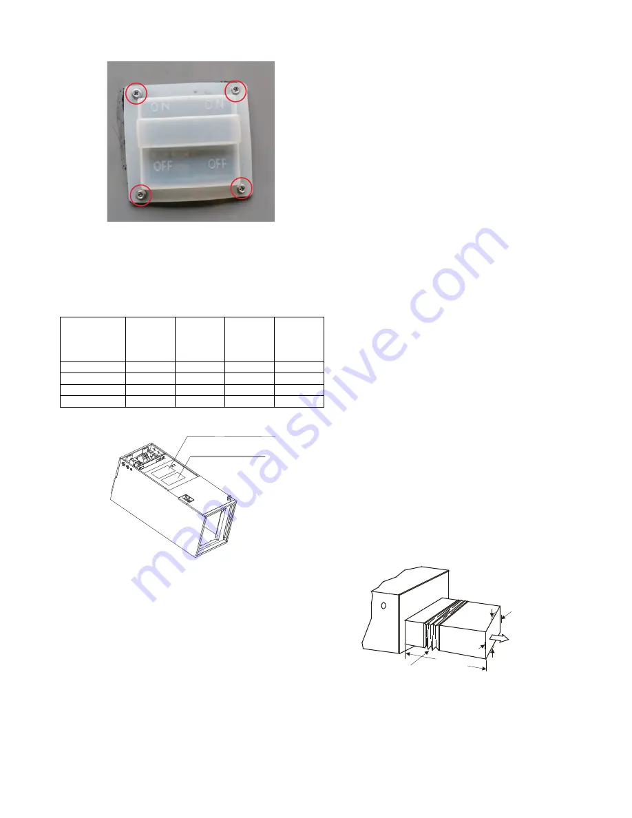
14. Fasten the resilient cap and seal on the upper cover plate with 4
screws.
Fig. 34 — Fasten the resilient cap
15. Reassemble the electronic control cover and secure it with screws.
Reassemble the upper cover plate and secure it with screws. After
the electric heating wiring is connected, confirm the plate is secure
before powering the unit on. Check all the wiring and ensure a
reliable connection with the wire body.
Table 6 — Specifications
Fig. 35 — Indoor Unit Wiring Diagram
NOTE:
The electric auxiliary heat wiring diagram is supplied with the
accessories. Please paste the wiring diagram in the designated position
after installing the heat modules.
Step 4 - Installing Ductwork
Connect the supply-air duct over the outside of the 3/4in (19 mm)
flanges provided on the supply-air opening. Secure the duct to the
flange, using proper fasteners for the type of duct used, and seal duct-
to-unit joint. If the return-air flanges are required, install the factory-
authorized accessory kit.
Use flexible connectors between the ductwork and unit to prevent
transmission of vibration. When the electric heater is installed, use
heat-resistant material for the flexible connector between the
ductwork and the unit at the discharge connection. Ductwork passing
through the unconditioned space must be insulated and covered with a
vapor barrier.
Units equipped with 20kW electric heaters require a 1in (25mm)
clearance to combustible materials for the first 36in (914mm) of
supply duct.
DUCTWORK ACOUSTICAL TREATMENT
Metal duct systems that do not have a 90 degree elbow and 10ft (3m) of
main duct to first branch takeoff may require internal acoustical insulation
lining. As an alternative, fibrous ductwork may be used if constructed and
installed in accordance with the latest edition of the SMACNA
construction standard on fibrous glass ducts. Both acoustical lining and
fibrous ductwork shall comply with the National Fire Protection
Association as tested by UL Standard 181 for Class 1 air ducts.
The air supply and return may be handled in one of several ways;
whichever situation is best suited for the installation (See Fig. 5 — on
page 5). A large number of issues encountered with split-system
installations can be linked to improperly designed or installed duct
systems. It is therefore very important that the duct system be properly
designed and installed.
Use of flexible duct collars is recommended to minimize the transmission
of vibration/noise into the conditioned space. Where the return air duct is
short, or where sound is liable to be a problem, sound absorbing glass fiber
should be used inside the duct.
Insulation of duct work must be installed according to local codes and
best practices. The supply air duct should be properly sized by use of a
transition to match unit opening.
This unit is not designed for non-ducted (freeblow) applications. Duct
work should be fabricated and installed in accordance with local and/
or national codes.
Fig. 36 — Flexible Duct Collar Connection
Specifications
No. of
Circuit
Breakers
No. of
Relays
No. of
Power
Cord
Groups
No. of
Power
Cord
Grounding
Screws
5kW
1
1
1
1
10kW
1
2
1
1
15kW
2
3
2
2
20kW
2
4
2
2
Indoor unit wiring diagram
Electric auxiliary
heat wiring diagram
Plenum Clearances
MINIMUM CLEARANCE
OF 1ft (25.4mm) ALL SIDES
RECOMMENDED FLEXIBLE
DUCT COLLAR
3.2ft (1m)


