Service Manual
, 2016-12
35
/
47
10.4
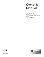
Fan motor circuit of the freezing chamber
12 V voltage is reduced to 7~12V through the control chip BD9227F ,output it to F-FAN pin and
connect it to positive pole of fan, to control the operating of fan in different revolution. Check the
voltage between F-FAN pin and GDN pin, to estimate the fan trouble.
10.5
Refrigerator fan motor circuit (None)
10.6
Condensing fan motor circuit (None)
10.7
Damper motor circuit (None)
10.8
Resistance value of the sensor (R/T)
Tx(
℃
)
R
(
KΩ
)
Tx(
℃
)
R
(
KΩ
)
Tx(
℃
)
R
(
KΩ
)
Tx(
℃
)
R
(
KΩ
)
Tx(
℃
)
R
(
KΩ
)
-30
33.81
-15
14.31
0
6.495
15
3.141
30
1.617
-29
31.85
-14
13.55
1
6.175
16
2.999
31
1.55
-28
30.01
-13
12.83
2
5.873
17
2.865
32
1.486
-27
28.29
-12
12.16
3
5.587
18
2.737
33
1.426
-26
26.68
-11
11.52
4
5.315
19
2.616
34
1.368
-25
25.17
-10
10.92
5
5.06
20
2.501
35
1.312
-24
23.76
-9
10.35
6
4.818
21
2.391
36
1.259
-23
22.43
-8
9.82
7
4.589
22
2.287
37
1.209
-22
21.18
-7
9.316
8
4.372
23
2.188
38
1.161
-21
20.01
-6
8.841
9
4.167
24
2.094
39
1.115
Summary of Contents for 22031010000841
Page 5: ...Service Manual 2016 12 5 47 1 Safety Warning Code 1 1Warning for operation safety...
Page 6: ...Service Manual 2016 12 6 47...
Page 7: ...Service Manual 2016 12 7 47...
Page 8: ...Service Manual 2016 12 8 47 1 2Safety instruction for refrigerant...
Page 37: ...Service Manual 2016 12 37 47 11 Troubleshooting Method 11 1 No refrigeration...
Page 38: ...Service Manual 2016 12 38 47 11 2 Compressor failure...
Page 39: ...Service Manual 2016 12 39 47 11 3 Defrosting is not working...