12
ENGLISH
VIII. GAS SUPPLY (gas ovens only)
A. Connection
NOTE:
It may be necessary to temporarily remove the rear cool
panels to connect the gas supply.
Check the ovens gas supply requirements before making the
gas utility connection. Gas supply requirements are listed on
the ovens serial plate (Figure 2-16) and in the Gas Orifice and
Pressure Specifications table (Page 4 of this manual).
Check the serial plate to determine the type of gas (Propane or
Natural) to be used with the oven.
Refer to the instructions in the gas hose package (included in
the Installation Kit) before connecting the gas line. One gas line
connection method is shown in Figure 2-18; however,
CAUTION
DURING PRESSURE TESTING NOTE ONE OF THE FOLLOW-
ING:
1. The oven and its individual shutoff valve must be
disconnected from the gas supply piping system during
any pressure testing of that system at test pressure in
excess of 1/2 psi (3.45 kPa).
2. The oven must be isolated from the gas supply piping
system by closing its individual manual shutoff valve
during any pressure testing of the gas supply piping
system at test pressure equal to or less than 1/2 psi (3.45
kPa).
3. If incoming pressure is over 14 W.C. (35mbar), a
separate regulator MUST be installed in the line BEFORE
the individual shutoff valve for the oven.
WARNING:
To prevent damage to the control valve
regulator during initial turn- on of gas, it is very important
to open the manual shutoff valve very slowly.
After the initial gas turn-on, the manual shutoff valve
must remain open except during pressure testing as
outlined in the above steps or when necessary during
service maintenance.
compliance with the applicable standards and regulations is
mandatory.
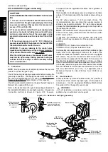
Inlet, regulated, and pilot gas pressure readings can be taken
using a U tube manometer at the tap locations shown in Figure
2-19.
One 90° elbow equals a 7 (2.13m) length of pipe. The
recommended pipe sizes are larger than usually required to
eliminate any operation problems. It is much less expensive
to make the initial installment large enough to do the job rather
than redoing the job later.
NOTE:
The installation must conform with local codes or in the
absence of local codes, with the National Fuel Gas Code, ANSI
Z223.1-latest edition.
In Australia, the installation must conform with AGA Code
AG601 and with any requirements of the appropriate statutory
authority.
CANADIAN:
CAN/CGA-B 149.1 Natural Gas Installation Code
CAN/CGA-B 149.2 Propane Installation Code
Certain safety code requirements exist for the installation of gas
ovens; refer to the beginning of Section 2 for a list of the
installation standards. In addition, because the oven is equipped
with casters, the gas line connection shall be made with a
connector that complies with the Standard for Connectors for
Movable Gas Appliances, ANSI Z21.69 (in U.S.A.), or, if appli-
cable, Connectors for Movable Gas Appliances, CAN/CGA-6.16
(in Canada), as well as a quick-disconnect device that complies
with the Standard for Quick-Disconnect Devices for Use With
Gas Fuel, ANSI Z21.41 (in U.S.A.), or, if applicable, Quick-
Disconnect Devices for Use With Gas Fuel, CAN1-6.9 (in
Canada).
B. Gas Conversion
Where permitted by local and national codes, it is possible to
convert ovens from natural to propane gas, or from propane to
natural gas. Use the appropriate Middleby Marshall Gas
Conversion Kit for the specific oven model.
WARNING
All installations, conversions and service work must be
performed by an authorized service agent.
Figure 2-19 - Gas Burner and Piping Assembly
Manual
shutoff valve
Pilot pressure tap
(where pilot gas
pressure is measured)
Combination Gas
Control Valve
(Safety Regulator)
Inlet pressure tap
(where incoming
gas pressure is
measured)
Manifold pressure tap
(where manifold gas
pressure is measured)
On/Off Knob
Always leave in
ON position
Low Flame
Bypass Line
High Flame
Solenoid Valve
Burner Blower
Gas Burner
SECTION 2 - INSTALLATION
All manuals and user guides at all-guides.com


