background image

50

Chapter 7: Operation

DL451 Modular I/O

Operator Manual

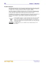
Replacing a module

The design of the DL451 Modular I/O makes module replacement very easy and 
straightforward.  The unit has rack guides in each of the three module positions so that 
the modules can slide easily in and out.  Each module is held in place by two screws, at 
the left- and right-hand sides, and a short metal post (or stud) adjacent to each screw 
facilitates removal.

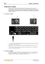
To remove a module

To remove a module

The fitting of a module is the reverse of the above procedure.  The unit will recognise 
the type and position of the new module just fitted.  However, you may need to 
configure some of its options; see Chapter 6 “Main Menu”.

1

Switch off unit and isolate it electrically from the mains power supply by removing the mains 

power cable from the rear of the unit.

2

Remove the two securing screws from the left- and right-hand sides of module (on rear 

panel).

3

Pull out the module using the two circular machined posts (fitted to rear of module panel, 

adjacent to the two securing screws).

2a

2b

1a

1b

Summary of Contents for DL451

Page 1: ...1562 745371 Email info uk telex com Website www midasconsoles com DL451 Modular I O Operator Manual DOC02 DL451 Issue 1 April 2007 Telex Communications UK Limited In line with the company s policy of...

Page 2: ......

Page 3: ...eat sources such as radiators heat registers stoves or other apparatus including amplifiers that produce heat 9 Do not defeat the safety purpose of the polarized or grounding type plug A polarized plu...

Page 4: ......

Page 5: ...ions of use which must be observed when these products are taken into service to maintain compliance with the above directives Details of these special measures and limitations to use are available on...

Page 6: ......

Page 7: ...nd international copyright and intellectual property laws and treaties All rights to copyrights trademarks and trade secrets in the Software or any modifications to it are owned by Company Unauthorize...

Page 8: ...for the Linux programs that have been provided with your Midas or Klark Teknik product send a check or money order no cash accepted your address and 10 00 to cover the cost of optical media postage a...

Page 9: ...zard do not expose the equipment to rain or moisture To avoid electrical shock do not remove covers Refer servicing to qualified personnel only The power supplies even the DC ones have a high current...

Page 10: ...et hands Handling the equipment Completely isolate the equipment electrically and disconnect all cables from the equipment before moving it When lifting or moving the equipment always take its size an...

Page 11: ...d to the console and where appropriate they should have Pin 1 connected to the cable screen Radio frequency interference Class A device This equipment has been tested and found to comply with the limi...

Page 12: ...r effectiveness has been reduced Optional equipment Unless advised otherwise optional equipment must only be installed by service personnel and in accordance with the appropriate assembly and usage re...

Page 13: ...ecklist 13 FOH and MON 14 Audio physical connections 15 Uses of the configurable audio connections 15 Mix matrix 17 Console linking 17 Input channel processing 17 Mix channel processing 18 Output chan...

Page 14: ...ersion number 45 Option 4 Software Vers 45 To view the unit s current host software version 45 Option 5 Digital boards 46 To set up the clock source for the digital outputs 46 To set up the SRC settin...

Page 15: ...tor Manual Appendix B Technical Specification 57 General specifications 57 Inputs and outputs 57 Analogue inputs 57 Analogue outputs 57 Digital inputs 58 Digital outputs 58 MIDI and GPIO 58 Digital sy...

Page 16: ...xvi DL451 Modular I O Operator Manual...

Page 17: ...y efficient manufacturing methods and will give you many years of reliable service So to obtain the best results with a minimum of effort please read this operator manual and finally enjoy your Midas...

Page 18: ...ckground information Document structure This manual is divided into the following sections Chapter 1 Introduction this chapter Introduction to the DL451 Modular I O unit and provides information on th...

Page 19: ...s a list of the main items contained in the DL451 Modular I O package 1 off DL451 Modular I O unit 1 off DL451 Modular I O operator manual this document part number DOC02 DL451 1 off warranty card par...

Page 20: ...4 Chapter 1 Introduction DL451 Modular I O Operator Manual...

Page 21: ...nt of any single failure of hardware or software To achieve this the system employs dual redundancy where a key component has a identical redundant spare that is ready to take over should it fail Othe...

Page 22: ...Console comes to you POP groups Console comes to you Muscle memory E zone on channel strip D zone on channel strip Paged controls do not change function Fast zone Electronic colour coding Dedicated m...

Page 23: ...trollers Control centre has five multiple redundant power supplies Stage box has integral dual power supplies Service and support 24 7 global telephone support Service support centres in US UK and Sin...

Page 24: ...ows straightforward interfacing with any third party hardware that also utilises this connection MidasNET connections carry digital audio control data and standard Ethernet traffic bidirectionally dow...

Page 25: ...connected to both routers The XL8 Control Centre which forms the core of the XL8 Live Performance System is connected to each router via a snake and also connects to a DN9331 RAPIDE Each router acts a...

Page 26: ...Stage rack 1 Note All connections are dual redundant so the system can operate quite normally using either the X or Y cables 5 4 3 2 1 6 7 8 9 10 5 4 3 2 1 6 7 8 9 10 5 4 3 2 1 6 7 8 9 10 1 5 4 3 2 1...

Page 27: ...control connectors to Ethernet control X connectors on DSP units Y router s Ethernet control connectors to Ethernet control Y connectors on DSP units Y router s AES50 audio bank 1 connectors to AES50...

Page 28: ...l Router Optical snake Carries a bi directional combination of 192 channels of 96KHz audio plus 200Mbs of control data Control centre Cat6e Router Cat6 snake Carries a bi directional combination of 19...

Page 29: ...of the XL8 Control Centre to one of the eight ETHERNET Ethercon XLR sockets on the rear of the RapidE unit Use the socket X or Y of the currently active network Routers Stage rack 1 units 2 x Mic Spli...

Page 30: ...h unit in a typical XL8 Live Performance System FOH and MON set up In particular it shows the how the FOH and MON sections are connected up notice that the mic splitters are shared between them Figure...

Page 31: ...ce System has a total configurable audio channel count on the DL451 I O units of between 120 and 240 depending on the mix of analogue and digital I O excluding the non configurable 96 mic inputs on th...

Page 32: ...720 Figure 3 shows a system configuration containing the extra nine DL451 I O units but does not show the redundant duplicated network All connectivity is controlled via the GUI 1 These spare AES50 po...

Page 33: ...l processing Each of the 96 full function input channels has Analogue and digital gain Phase reverse switch Input delay Swept high pass filter with choice of two filter slopes Swept low pass filter wi...

Page 34: ...onal 31 band GEQ replaces PEQ Frequency conscious compressor with soft clip limiter and choice of five compression styles Insert point Routing via level controls to the 16 matrix buses Routing via pan...

Page 35: ...d 16 effects processors as standard The 16 effects processors can be freely chosen from KT DN780 reverb Stereo delay Stereo flanger Stereo phaser The 16 mono KT GEQs can be patched into any output The...

Page 36: ...USB keyboard input sockets at the front of the control centre under the left and right hand modules allow the input and mix screens to be controlled via an external keyboard should the output module s...

Page 37: ...l bay processor Dual redundant internal router Dual redundant internal master controller Local I O units Mic splitters shared This diagram gives a more detailed illustration of the interconnections in...

Page 38: ...its Mic splitters shared DSP units This diagram illustrates an extreme example of dual redundancy in a standard FOH and stage monitor set up where one half of the system is down Please note this is a...

Page 39: ...processor Internal router Internal master controller Local I O units Mic splitters shared This diagram illustrates the effects of a single router failure in an FOH and stage monitor set up Figure 6 S...

Page 40: ...d hardware remotely via the MidasNET from a standard Ethernet connection This opens up many opportunities to use the network for transmitting control data as well as digital audio The XL8 Control Cent...

Page 41: ...his document Contains quick set up and operation instructions for the XL8 Live Performance System and XL8 Control Centre Hard copy wire O bound DOC04 XL8 XL8 Control Centre Operator Manual this docume...

Page 42: ...26 Chapter 2 XL8 Live Performance System Overview DL451 Modular I O Operator Manual...

Page 43: ...l monitors see page 28 5 Control panel containing LCD display and four pushbuttons see page 27 6 Three rows of eight write on strips for manually marking the A B or C module analogue digital channel a...

Page 44: ...ular voltage supply that is 18V 18V 5V 3 3V and 48V Ethernet control panel The Ethernet control panel has two green LEDs X and Y which have three states of illumination to indicate Flashing active mas...

Page 45: ...ule shown in slot A see DL441 analogue input module on page 31 DL442 analogue output module shown in slot B see DL442 analogue output module on page 32 DL452 digital in out AES EBU module shown in slo...

Page 46: ...SB slave type B and host type A sockets for connection of a laptop PC 4 Three MIDI musical instrument digital interface sockets in out and thru for connection of a musical instrument such as a synthes...

Page 47: ...vision for gain adjustment in 5dB steps from 5dB to 40dB This allows very high signal levels to enter the system and means that the same hardware can be used for mic inputs if required by the system W...

Page 48: ...uses eight output XLRs each having check and mute LEDs The line outputs have no analogue level adjustment 2 3 1 1 Eight XLR analogue outputs 2 Green check LED illuminates to indicate when a channel is...

Page 49: ...using an SRC There are two potential clock sources for the digital outputs the system and the coinciding digital input When using the system to drive the digital outputs the output SRC is bypassed an...

Page 50: ...34 Chapter 4 Rear Panel DL451 Modular I O Operator Manual...

Page 51: ...kets on the X and Y routers Ethernet connect the Ethernet control X and Y sockets to the appropriate Ethernet control sockets on the X and Y routers MIDI connect the three MIDI 5 pin DIN connectors if...

Page 52: ...tting up of the DL451 Modular I O involves allocating an ID for it within the XL8 network system environment see To set up the unit s ID on page 44 Configuration Configure the DL451 Modular I O unit t...

Page 53: ...he method of synchronising the AES50 See page 43 Option 2 2 Set ID for setting up the DL451 Modular I O s network unit ID See page 44 Option 3 3 CBMA Version for viewing the DL451 Modular I O s CBMA v...

Page 54: ...Main menu flowchart options 1 to 4 Default screen Press and hold for about two seconds Option 1 Option 2 A A B C D C D Option 3 Option 4 E This option does not appear if there are no digital I O boar...

Page 55: ...ithout saving any changes This flowchart only shows the down arrow presses Pressing the up arrow takes you in the opposite direction to a down arrow press 1 2 Non flashing options are currently select...

Page 56: ...Select from channels 1 2 3 4 5 6 and 7 8 F G This option does not appear if there are no digital boards fitted This action occurs even if there is no digital board fitted in selected board position Pr...

Page 57: ...Main menu options 41 DL451 Modular I O Operator Manual Select from OUTPUT and INPUT SRC settings for Ch1 2 3 4 5 6 and 7 8 Above options show OUTPUT SRC Ch1 2 selected as an example F option G option...

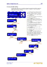
Page 58: ...n menu by one level To exit the main menu press the MENU button as many times as necessary until you are back at the default screen The DL451 Modular I O will exit the main menu automatically after ab...

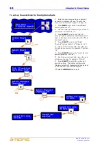
Page 59: ...in menu and select an option on page 42 You should see the AES clock select menu shown left which shows the current clock source 2 Press the down arrow to go to the other option 3 At the option you re...

Page 60: ...own left which shows the current ID 2 Use down arrow button to go to the ID number you require for example 7 If you wish to leave the current selection unchanged at this point select the Unchanged opt...

Page 61: ...the DL451 Modular I O unit is running To view the unit s current host software version 1 Enter the main menu and select option 3 see To enter the main menu and select an option on page 42 You should...

Page 62: ...1 Enter the main menu and go to option 5 as shown in diagram left see To enter the main menu and select an option on page 42 2 Press MENU to go to the Select Board options default is A 3 Use the down...

Page 63: ...example C 4 Press SELECT to go to the Dig IO settings options default is Clock Setup out and use the down arrow button to go the SRC options display 5 Press SELECT to go to the SRC settings options de...

Page 64: ...s Clock Setup out and use the down arrow button to go the Word Size out option 5 Press SELECT to go to the Select Channels options default is Channels 1 2 6 Use the down arrow button to go the pair of...

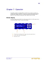
Page 65: ...51 Modular I O as it is operated solely from the XL8 Control Centre please refer to its operator manual part number DOC02 XL8 for details Default display The default display appears after the unit has...

Page 66: ...oval To remove a module To remove a module The fitting of a module is the reverse of the above procedure The unit will recognise the type and position of the new module just fitted However you may nee...

Page 67: ...t care not to damage the pushbuttons etc To clean the LCD screen see Cleaning the LCD display on page 51 Cleaning the LCD display Carefully wipe the surface of the LCD display with a soft lint free cl...

Page 68: ...ent during their life times and when they become waste The WEEE directive addresses the disposal of products when they have reached the end of their life and contributes to the reduction of wasteful c...

Page 69: ...k Diagram Analogue input module DL441 Line mic board details ADDRESS DATA SYSTEM WORD CLOCK LOCAL PLL A D HPF DIGITAL OUT REMOTE CONTROL INTERFACE 48V STATUS LED MIC LINE INPUT 1 OF 8 CHANNEL PATHS DI...

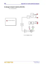
Page 70: ...perator Manual Analogue output module DL442 Line out board details ADDRESS DATA SYSTEM WORD CLOCK LOCAL PLL D A Lo Pass Filter DIGITAL IN REMOTE CONTROL INTERFACE MUTE STATUS LED LINE OUT 1 OF 8 CHANN...

Page 71: ...REMOTE INTERROGATE LED 1 OF 4 CHANNELS DIGITAL BACKPLANE SIGNALS SYNC STATUS LED Digital Audio Out 12S Digital Audio In ADDRESS DATA SYSTEM CONTROL FPGA Digital Audio Transmitter 12S Digital Audio SRC...

Page 72: ...56 Appendix A Functional Block Diagram DL451 Modular I O Operator Manual...

Page 73: ...er DOC02 XL8 Due to a policy of continual improvement Midas reserves the right to alter the function or specification at any time without notice General specifications Inputs and outputs Analogue inpu...

Page 74: ...digital audio on 3 pin XLR Sample rates 48k 96k or auto tracking to inputs Bypass Sample rate converter can be bypassed Word length 16 20 or 24 bit MIDI connector In out and through on 5 pin DIN GPIO...

Page 75: ...our comments Our contact details can be found at the front of this manual More detailed information on the XL8 Live Performance System can be found in the XL8 Control Centre Operator Manual part numbe...

Page 76: ...k Teknik Building Walter Nash Road Kidderminster Worcestershire DY11 7HJ England Tel 44 1562 741515 Fax 44 1562 745371 Email info uk telex com Website www midasconsoles com 2007 Telex Communications U...

Reviews: