background image

Chapter 3 Horizontal System


21 

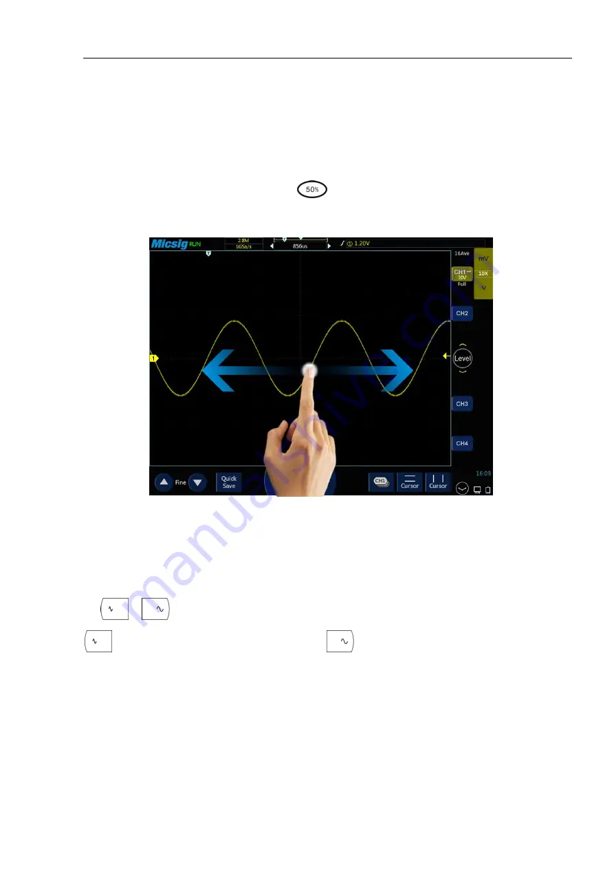
3.1 Move the Waveform Horizontally   

Put one finger on the waveform display area to swipe left and right, for the coarse adjustment of the waveform 

position horizontally of all analog channels; after moving the waveform, tap the fine adjustment button in the 

lower left corner of the screen for fine adjustment. 

After moving the channel left and right, tap the 

  key and select "time base" to quickly move the trigger 

position of the current channel to the center position in the horizontal direction. 


Figure 3-2 Move the Waveform Horizontally on the Screen 

3.2 Adjust the Horizontal Time Base (time/div)   

Method 1: Soft Keys 

Tap

  , 

  buttons to  adjust  the  horizontal  time  base  of  all  analog  channels (current  channels). Tap 

  button to increase the horizontal time base; tap 

  button to zoom out the horizontal time base (see 

Figure 3-3 Adjust the Horizontal Time Base). The horizontal time base is stepped in 1-2-5, while the waveform 

changes as the time base changes. 

Summary of Contents for TO1072

Page 1: ......

Page 2: ...Version Info Version Date Remarks V1 0 2016 10 V2 0 2020 04 ...

Page 3: ...ead this manual carefully before use and particularly pay attention to the Safety Precautions If you have read this manual please keep it properly for future reference The information contained herein are furnished in an as is state and may be subject to change in future versions without notice ...

Page 4: ...1 LOAD FACTORY SETTINGS 17 2 12 USE AUTO CALIBRATION 17 2 13 PASSIVE PROBE COMPENSATION 17 2 15 MODIFY THE LANGUAGE 19 CHAPTER 3 HORIZONTAL SYSTEM 20 3 1 MOVE THE WAVEFORM HORIZONTALLY 21 3 2 ADJUST THE HORIZONTAL TIME BASE TIME DIV 21 3 3 PAN AND ZOOM SINGLE OR STOPPED ACQUISITIONS 23 3 4 ROLL XY 23 3 5 ZOOM MODE 26 CHAPTER 4 VERTICAL SYSTEM 29 4 1 OPEN CLOSE WAVEFORM CHANNEL MATH REFERENCE WAVEF...

Page 5: ...TER 8 MATH AND REFERENCE 79 8 1 DUAL WAVEFORM CALCULATION 80 8 2 FFT MEASUREMENT 82 8 3 REFERENCE WAVEFORM CALL 85 CHAPTER 9 DISPLAY SETTINGS AND FUNCTION BUTTONS 88 9 1 WAVEFORM SETTINGS 89 9 2 GRATICULE SETTING 89 9 3 PERSISTENCE SETTING 89 9 4 HORIZONTAL EXPANSION CENTER 90 9 5 TIME BASE MODE SELECTION 90 9 6 WAVEFORM REFRESH RATE HIGH REFRESH MODE 91 9 7 RUN STOP AND SINGLE SEQ 91 9 8 AUTO 91 ...

Page 6: ...6 12 7 1553B BUS TRIGGER AND DECODE 139 CHAPTER 13 REMOTE CONTROL 143 13 1 HOST COMPUTER 144 13 1 1 Installation of Host Computer Software 144 13 1 2 Connection of Host Computer 144 13 1 3 Main Interface Introduction 145 13 1 4 Operation Interface Introduction 146 13 1 5 Storage and View of Pictures and Videos 146 13 2 MOBILE REMOTE CONTROL 147 13 3 FTP 148 13 4 SCPI 151 CHAPTER 14 REFERENCE 152 1...

Page 7: ... earth ground Observe all terminal ratings To avoid fire or shock hazard observe all rating and markings on the product Consult the product manual for further information of ratings before making connections to the product User correct probes To avoid excessive electric shock use only correct rated probes for any measurement Disconnect AC power The adapter can be disconnected from AC power and the...

Page 8: ...ed to the circuit with a line voltage greater than 300Vrms Instantaneous overvoltage is present in circuits that are isolated from the mains supply The TO1000 series digital oscilloscope is designed to safely withstand sporadic transient overvoltage up to 1000Vpk Do not use this equipment for any measurements in circuits where the instantaneous overvoltage exceeds this value 1 2 Safety Terms and S...

Page 9: ...ed scope Warning If the instrument input port is connected to a circuit with the peak voltage higher than 42V or the power exceeding 4800VA to avoid electric shock or fire User only insulated voltage probes supplied with the instrument or the equivalent product indicated in the schedule Before use inspect voltage probes test leads and accessories for mechanical damage and replace when damaged Remo...

Page 10: ...f settings and related calibration requirements of the tBook mini series oscilloscope Inspect package contents Use bracket Rear panel side panel Front panel Power on off the oscilloscope Understand the oscilloscope display interface Introduction to basic operations of oscilloscope Mouse operation Connect probe to the oscilloscope Use automatic Use factory settings Use auto calibration Passive prob...

Page 11: ...complete If the accessories are missing or damaged please contact Micsig s agent or local office 3 Inspect the instrument If any damage to oscilloscope is found by the appearance inspection or it fails to pass the performance test please contact Micsig s agent or local office If the instrument is damaged due to transportation please retain the package and contact the transportation company or Mics...

Page 12: ...Chapter 2 Quick Start Guide of Oscilloscope 9 2 3 Rear panel side panel Figure 2 2 Rear panel side Panel 2 4 Front Panel Figure 2 3 Front Panel of Tablet Oscilloscope ...

Page 13: ... adjusts to the center of the screen on both sides horizontal or vertical Measure Touch to turn on off measurement menu Trigger Touch to turn on off trigger menu Home Touch to return to the homepage Table 2 1 Description of Oscilloscope Front Panel 2 5 Power on off the Oscilloscope Power on off the oscilloscope First time start Connect power adapter to the oscilloscope and the oscilloscope should ...

Page 14: ...stments will be detailed in subsequent chapters and sections The following items may appear on the screen at a given time but not all items are visible The oscilloscope interface is shown in Figure 2 4 Figure 2 4 Oscilloscope Interface Display No Description 1 Micsig logo 2 Oscilloscope status including RUN STOP WAIT AUTO 3 Trigger point 4 Sampling rate memory depth 5 The area in indicates the pos...

Page 15: ... close 17 Current channel selection Click to pop up the current channel switching menu to switch the current channel 18 Horizontal time base control icon Tap the left right time base buttons to adjust the horizontal time base of the waveform Tap the time base to turn on the time base knob and turn the knob to adjust the time base 19 Quick save Tap to quickly save the waveform as a reference wavefo...

Page 16: ...n Tap any blank space on the screen to exit the menu Swipe Single finger swipe to open close menus including main menu shortcut menu button and other channel menu operations For example the main menu is opened as shown in Figure 2 6 The closing method is the opposite of the opening method Figure 2 6 Slide out of Main Menu Tap the options in the main menu to enter the corresponding submenu ...

Page 17: ...al Position for details 2 8 Mouse Operation Connect the mouse to the USB Host interface then operate the oscilloscope with the mouse The menu will pop up with the right mouse button The left mouse button has the same function as the finger touch and the horizontal time base can be adjusted by rolling the mouse wheel The right mouse button menu is shown in Figure 2 7 Figure 2 7 Mouse Cursor 2 9 Con...

Page 18: ...or closed automatically according to the set threshold level The threshold level can be settable Source can be automatically triggered and the triggered source channel can be automatically set to select priority to the current signal or to the maximum signal Open the main menu Tap Auto to open the auto set menu including channel open close setting threshold voltage setting and trigger source setti...

Page 19: ...t various parameters including vertical scale horizontal time base trigger level etc When the signal is connected these parameters will automatically change and the signal does not need to be operated again after the change The oscilloscope will automatically recognize and make the appropriate changes Auto range Turn the auto range function on or off Vertical scale Turn on the vertical scale autom...

Page 20: ... in red and after calibrating is finished the word in red disappears When the temperature changes largely the auto calibration function can make the oscilloscope maintain the highest accuracy of measurement Auto calibration should be done without probe Auto calibration process takes about two minutes If the temperature changes above 10 we recommended users perform the auto calibration 2 13 Passive...

Page 21: ... or manually adjust the waveform vertical sensitivity and horizontal time base Observe the shape of the waveform see Figure 2 14 Figure 2 14 Probe Compensation If the waveform on the screen is shown as under compensation or over compensation please adjust the trimmer capacitor until the waveform shown on the screen as correct compensation The probe adjustment is shown in Figure 2 15 ...

Page 22: ... 4 of a 4 channel oscilloscope 7 Repeat this step for each channel Warning Ensure the wire insulation is in good condition to avoid probe electric shock while measuring high voltage Keep your fingers behind the probe safety ring to prevent electric shock When the probe is connected a voltage source do not touch metal parts of the probe head to prevent electric shock Before any measurement please c...

Page 23: ... You are recommended to read this chapter carefully to understand the set functions and operation of the horizontal system of the tBook mini series oscilloscope Move the waveform horizontally Adjust the horizontal time base time div Pan and zoom single or stopped acquisitions Roll XY Zoom mode Figure 3 1 Horizontal system ...

Page 24: ...e key and select time base to quickly move the trigger position of the current channel to the center position in the horizontal direction Figure 3 2 Move the Waveform Horizontally on the Screen 3 2 Adjust the Horizontal Time Base time div Method 1 Soft Keys Tap buttons to adjust the horizontal time base of all analog channels current channels Tap button to increase the horizontal time base tap but...

Page 25: ...2 Time Base Knob Tap to turn on the time base knob see Figure 3 4 horizontal time base knob and then turn the knob to adjust the appropriate time base The time base shown on the left is the currently selected time base Figure 3 4 Horizontal Time Base Knob ...

Page 26: ... YT mode the relative relationship between vertical voltage and horizontal time is displayed Y axis represents the voltage X axis represents the time and the waveform is displayed after triggering waveform displayed from left to right Note When the time base is large such as 200ms and above sometimes the waveform will not be displayed for a long time this is because in YT mode the waveform must be...

Page 27: ...es below 5 Hz ROLL mode is defaulted as open When the time base is greater than 100ms it automatically enters the ROLL mode If the signal to be triggered under a large time base needs to be viewed turn off the ROLL mode Roll mode on and off In the main menu tap the soft key In the General option you can turn the roll mode on and off refer to Figure 3 7 When the roll mode is on and the time base is...

Page 28: ...aveform in XY mode Figure 3 8 XY Mode XY Mode Example This exercise shows the usual practice of XY display mode by measuring the phase difference between two signals of the same frequency using the Lissajous method 1 Connect sine wave signals to CH1 and connect sine wave signals of the same frequency and different phases to CH2 2 Press Auto set button tap Display in the main menu then select XY in...

Page 29: ...y2 cursors to the intersection point of the signal and the y axis Record the Δy value again Figure 3 10 Phase Difference Measurement and Using the Cursor 7 The following formula is used to calculate the phase difference For example if the first Δy value is 9 97V the second Δy value is 5 72V Error Reference source was not found phase difference error Reference source was not found 3 5 Zoom Mode Zoo...

Page 30: ...ce Zoom window view is the enlarged portion of the normal display window You can use Zoom to view a portion of the normal window that is horizontally expanded to learn more about signal analysis Zoom on off 1 Open the pull up menu and tap button to turn the zoom function on off 2 Put three fingers on the touch screen at the same time slide down to open zoom mode slide up to turn off zoom mode Figu...

Page 31: ...drag the box in the normal window to quickly locate the waveform to be viewed Note 1 The minimum time base is displayed in the normal window when the waveform in the screen is exactly within the memory depth If the current time base is smaller than the minimum time base in the normal window at the current memory depth when the zoom window is opened the time base in the normal window is automatical...

Page 32: ...log channel math function set the current channel Adjust vertical sensitivity Adjust vertical position Open channel menu Set channel coupling Set bandwidth limit Waveform inversion Set probe type Set probe attenuation coefficient Vertical expansion reference The figure below shows the CH1 Channel Menu displayed after opening the CH1 channel menu Figure 4 1 Channel Menu Display Interface The ground...

Page 33: ...hat is preferentially displayed on the uppermost layer is called the current channel The channel indicator for the current channel is solid and the channel indicator for the non current channel is hollow as shown in Figure 4 2 Figure 4 2 Current Channel and Non Current Channel The display content of the oscilloscope channel display interface includes the sampling mode vertical scale vertical scale...

Page 34: ... the button to light it up as shown in Figure 4 5 Tap the button in the menu to switch the current channel When this function is opened a the current channel may be switched in the channel switching menu b the current channel menu can be moved anywhere on the screen c only the open channel is displayed in the channel switching menu d when the math or reference waveform is opened the current channe...

Page 35: ...cal sensitivity range of 1 1 probe is 1mV div 10V div optionally minimum at 500uV div 4 3 Adjust Vertical Position The method of adjusting vertical position is as follows 1 Coarse adjustment In the waveform display area hold the waveform and put one finger to slide up and down for changing the vertical position of the waveform 2 Fine adjustment After the waveform moves vertically click the fine ad...

Page 36: ...AC and GND channel coupling modes in the pop up box DC DC coupling Both the DC component and the AC component of the measured signal can pass and can be used to view waveforms as low as 0 Hz without large DC offset AC AC coupling Measured DC signal is blocked and only the AC component can be allowed to pass and used to view waveforms with large DC offsets GND Internal input ground disconnecting fr...

Page 37: ...34 Figure 4 8 DC Coupling Figure 4 9 AC Coupling ...

Page 38: ...z are effectively attenuated High Pass Only signals above the lower limit of the currently set frequency are allowed to pass Select high pass tap the frequency box open the frequency setting interface tap MHz and KHz to select the frequency scale drag or tap the slide bar for coarse adjustment of the maximum frequency allowed to pass tap buttons to precisely adjust the frequency Low pass Only sign...

Page 39: ... Pass Figure 4 14 Low Pass 4 4 3 Waveform Inversion After selecting Invert the voltage value of the displayed waveform is inverted Inversion affects the way the channel is displayed When using a basic trigger you need to adjust the trigger level to keep the waveform stable ...

Page 40: ...r Inversion 4 4 4 Set Probe Type Probe types are divided into voltage probe and current probe Probe type adjustment steps Open the channel menu find the Probe Type checkbox in the channel menu then select Vol corresponding the voltage probe Cur corresponding the current probe ...

Page 41: ...ing attenuation ratio must be set on the channel menu to ensure the correctness of the waveform amplitude and measurement result displayed by the oscilloscope Probe attenuation ratio and menu attenuation ratio are shown in the table below Probe attenuation ratio Menu attenuation ratio 0 001 1 1mx 0 002 1 2mx 0 005 1 5mx 0 01 1 10mx 0 02 1 20mx 0 05 1 50mx 0 1 1 100mx 0 2 1 200mx 0 5 1 500mx 1 1 1x...

Page 42: ...loscope You are recommended to read this chapter carefully to understand the set functions and operation of the trigger system of the tBook mini series oscilloscope Trigger and trigger adjustment Edge trigger Pulse width trigger Logic trigger Nth edge trigger Runt trigger Slope trigger Time out trigger Video trigger Serial bus trigger ...

Page 43: ...he waveform according to the condition is Trigger The so called capture waveform is that the oscilloscope grabs a signal and displays it If it is not triggered there is no waveform display What can Trigger be used for 1 The oscilloscope can stably display a periodic signal Figure 5 1 Stably Displayed Periodic Signal Figure 5 2 Non Stably Displayed Periodic Signal ...

Page 44: ...matic oscilloscope trigger is the forced trigger It means that the oscilloscope only grabs a signal segment for display regardless of whether the condition is met or not Automatic forced trigger is set in the menu In the trigger settings there is usually a trigger mode option which can be set as Normal or Auto Normal trigger means trigger after meeting the set condition Automatic trigger is a kind...

Page 45: ...e from automatic forced trigger Figure 5 6 shows a conceptual demonstration of the acquisition memory In order to understand the trigger event the acquisition memory can be divided into pre trigger and post trigger buffers The position of the trigger event in the acquisition memory is defined by the time reference point and trigger position horizontal delay settings Figure 5 6 Conceptual Demonstra...

Page 46: ...on the right side to the time reference point and the delay time is displayed as a negative value the trigger point overlaps with the center line of the waveform display area and the delay time is zero Trigger level Trigger level is the signal voltage corresponding to the set trigger point When the trigger level is changed a horizontal line will appear temporarily on the screen to tell you the lev...

Page 47: ...eform amplitude of the trigger source channel Set trigger hold off time The trigger rejection time can set up the waiting time of the oscilloscope after the trigger and before the trigger circuit is reconnected During rejection the oscilloscope does not re trigger until the end of the rejection time and the rejection time can be used to stably trigger complex waveforms The trigger rejection time r...

Page 48: ...petitive waveform Changing the time base setting will not affect the trigger rejection time Using Zoom function you can tap Run Stop to stop then horizontally move and zoom the data to find the position where the waveform is repeated Use the cursor to measure this time and then set the rejection time Use SingleSEQ button for single acquisition Usually when performing a single acquisition you must ...

Page 49: ...oupling DC AC and DC components getting through trigger signals AC Filter out the DC component of trigger signals HF rejection Suppress signals above 50KHz in trigger signals LF rejection Suppresses signals below 50KHz in trigger signals Noise rejection Low sensitivity DC coupling to suppress high frequency noise in trigger signals Set CH1 rising edge trigger and coupling as DC with operation step...

Page 50: ...requencies that can interfere with correct trigger When there is low frequency noise in the waveform stable edge triggering can be obtained using LF rejection coupling 5 NoiseRej Noise Rejection Coupling Noise rejection can add extra hysteresis to the trigger circuit By increasing the trigger hysteresis band the possibility of noise triggering can be reduced But it also reduces the trigger sensiti...

Page 51: ...ger Pulse Width 8ns 10s Set the trigger pulse width Notes Conditions of greater than smaller than equal to or not equal to indicating that the error is 6 Trigger steps of positive polarity pulse width taking CH1 as an example 1 Tap Trigger on the main menu to open the trigger menu select the pulse width trigger in the trigger type and set the pulse width trigger as follows as shown in Figure 5 13 ...

Page 52: ...ictions are true the trigger will happen on the high to low transition of the pulse when triggered on negative polarity pulse if the restrictions are true the trigger will happen on the low to high transition Figure 5 14 Negative Pulse Level Flip Figure 5 14 Negative Polarity Pulse Level Flip 2 Trigger condition and pulse width time setting Time restrictions that can set in the trigger condition S...

Page 53: ... to 80ns Figure 5 17 Trigger Time T 80ns Figure 5 17 Trigger Time T 80ns Not equal to the time value For example for positive pulse if it is set as T 80ns the trigger will happen stably only when the pulse width is not equal to 80ns Figure 5 18 Trigger Time T 80ns Figure 5 18 Trigger Time T 80ns The trigger pulse width time can be set as 8ns 10s Tap the pulse width time setting box to pop up the t...

Page 54: ...ow Set CH1 as low None Set CH1 as none CH2 High Set CH2 as high Low Set CH2 as low None Set CH2 as none CH3 High Set CH3 as high Low Set CH3 as low None Set CH3 as none CH4 High Set CH4 as high Low Set CH4 as low None Set CH4 as none Trigger Logic AND Select the logic of trigger source as AND OR Select the logic of trigger source as OR NAND Select the logic of trigger source as NAND NOR Select the...

Page 55: ...ation Logic gate AND Condition Logic time 400ns Figure 5 20 Logic Trigger Setting Menu Logic trigger setting description Logic level setting After trigger source select High Low and None for the channel The corresponding trigger level value is displayed in the upper right corner of the display screen High means a value higher than the current trigger level and the icon indication is Low means a va...

Page 56: ...h edge trigger are shown in the table below Trigger Option Setting Description Trigger Source CH1 Set CH1 as trigger signal source CH2 Set CH2 as trigger signal source CH3 Set CH3 as trigger signal source CH4 Set CH4 as trigger signal source Time 8ns 10s Idle time Edge Rising edge Set signal trigger on the rising edge Falling edge Set signal trigger on the falling edge Nth Edge 1 65535 Set trigger...

Page 57: ...as shown in Figure 5 22 Trigger source CH1 Time 10ms Edge signal rising Nth edge 3 Figure 6 22 Nth Edge Trigger Menu 2 Adjust the trigger level to ensure that the waveform can be triggered stably for example the trigger level is set to 3 2V ...

Page 58: ...trigger signal source CH4 Set CH4 as trigger signal source Polarity Positive Set signal to trigger on positive runt pulse Negative Set signal to trigger on negative runt pulse Any Set signal to trigger on either positive or negative runt pulse Trigger Condition T Trigger when the signal pulse width is smaller than pulse width T T Trigger when the signal pulse width is greater than pulse width T T ...

Page 59: ... shown in Figure 5 25 Figure 5 25 Positive Negative Slope Time When the trigger signal slope has the hold time 8ns 10s the trigger type on the top of the screen is only the icon and trigger happens when the set condition is reached Slope trigger is suitable for observing sawtooth or triangular waves The slope trigger menu descriptions are shown in the table below Trigger Option Setting Description...

Page 60: ...nal slope hold time is greater than T T Trigger when the signal slope hold time is smaller than upper limit T1 and greater than lower limit T2 Time 8ns 10s Set the trigger signal slope hold time Set CH1 slope status as rise and hold time less than 1ms The steps are as follows 1 Tap Trigger on the main menu to open the trigger menu select the slope trigger in the trigger type and set the slope trig...

Page 61: ...btained by selecting the channel to which signals are connected as trigger source 5 8 Timeout Trigger Timeout trigger happens when the time from the intersection of signal and trigger level and above or below the trigger level reaches the set time as shown in Figure 5 27 Figure 5 27 Timeout Trigger Schematics Duration Set Level ...

Page 62: ...o count time when the falling edge of input signal gets through the trigger level Any Select to count time when the rising edge or falling edge of input signal gets through the trigger level Time 8ns 10s Timeout time Set the polarity of CH1 trigger signal to be positive and the timeout time as 15us The steps are as follows 1 Tap Trigger on the main menu to open the trigger menu select timeout trig...

Page 63: ...nu descriptions are shown in the table below Trigger Option Setting Description Trigger Source CH1 Set CH1 as trigger signal source CH2 Set CH2 as trigger signal source CH3 Set CH3 as trigger signal source CH4 Set CH4 as trigger signal source Polarity Positive Set signal positive polarity trigger Negative Set signal negative polarity trigger Video Standard 625 PAL Based on PAL signal trigger SECAM...

Page 64: ... all horizontal sync pulses Line 625 line PAL SECAM Trigger on a specified line in odd or even fields 263 odd line 262 even line NTSC 750 line 720P 1125 line 1080I 1080P Set CH1 as trigger channel positive polarity NTSC standard video all fields trigger and the steps are as follows 1 Tap Trigger on the main menu to open the trigger menu select the video trigger in the trigger type and set the vide...

Page 65: ...he video signal since the digital oscilloscope has multi level gray scale display function different brightness can reflect the frequency of different parts of the signal Experienced users can quickly judge the quality of the signal during the debugging process and find abnormal conditions 5 10 Serial Bus Trigger Please refer to Chapter 12 Serial Bus Trigger and Decode Optional ...

Page 66: ...e detailed information of the analysis system of the oscilloscope You are recommended to read this chapter carefully to understand the set functions and operation of the analysis system of the tBook mini series oscilloscope Automatic measurement Frequency meter measurement Cursor ...

Page 67: ...enu 2 Select measurement Select the desired measurement item on the measurement menu The selected measurement item is displayed in the Selected Parameters display area below 3 Press button on the key area to quickly close the measurement menu 4 Cancel measurement item In the Selected Parameters display area below measurement menu tap the measurement item to be cleared or tap button to clear all me...

Page 68: ...other channels as shown in Figure 6 3 click again to turn off all measurements Figure 6 2 Pull up Menu Figure 6 3 All Measurements Period Time of the first complete signal cycle in the waveform Frequency Reciprocal to the cycle time Rise time Time required for the first rising edge of the waveform to rise from the amplitude of 10 to 90 Fall time Time required for the first falling edge of the wave...

Page 69: ... selected between each channel and math channel There are four edge selections FirstRise FirstFall LastRise LastFall 4 Tap button to confirm Positive duty cycle Measured value of the first cycle in the waveform Positive duty cycle waveform positive pulse width period 100 Negative duty cycle Measured value of the first cycle in the waveform Negative duty cycle waveform negative pulse width period 1...

Page 70: ...ts The channel probe type setting is used to set the measurement unit for each input channel to Volts or Amperes Refer to 4 4 4 Set Probe Type High Take 100 in the entire waveform and calculated using either the min max or histogram method Low Take 0 in the entire waveform and calculated using either the min max or histogram method Max Highest positive peak measured over the entire waveform Min Hi...

Page 71: ...6 2 Frequency Meter Measurement Open the main menu tap Frequency Meter to enter the hardware frequency meter setting menu and select the channel to be measured as shown in Figure 6 5 The measured value is displayed in the upper left corner of the screen as shown in Figure 6 6 Figure 6 5 Frequency Meter Measurement Menu Open Figure 6 6 Frequency Meter Measurement 6 3 Cursor Open cursor and place it...

Page 72: ...vertical cursors relative to the trigger point 1 X frequency S reading Indicates the quotient of voltage difference of horizontal cursors and Δ time difference of vertical cursors that is the slope of the intersection of the four cursors Vertical cursor on off and activation Vertical cursor on off Vertical cursor on Tap cursor icon to open vertical cursors and the icon is on and activated Vertical...

Page 73: ...less the initial two fingers leave the screen If one finger leaves the screen and the other finger does not leave the current linkage adjustment is continued 3 Open the cursor tap select the cursor item and the cursor will automatically adjust to the center position of the screen on both sides of the horizontal or vertical Horizontal cursor on off and activation Horizontal cursor on off switching ...

Page 74: ...er 6 Analysis System 71 Figure 6 9 Cursor Measurement Pulse Width In the XY horizontal mode X cursor displays CH1 value V or A and Y cursor displays CH2 value V or A Figure 6 10 In XY Mode Cursor Measurement ...

Page 75: ... the detailed information of the screen capture function and memory depth of the oscilloscope You are recommended to read this chapter carefully to understand the storage system of the tBook mini series oscilloscope Screen capture function Video recording Memory depth Waveform storage ...

Page 76: ...rom the bottom to open the pull up menu Tap the icon to have a screen capture Figure 7 1 Screen Capture Please refer to 11 6 Photo for details on viewing pictures 7 2 Video Recording The video recording function is similar to the screen capture function which can store the display information of the current display to the local or U disk in video format When the U disk is not inserted the file is ...

Page 77: ...in USB device The file type can be WAV CSV or BIN The oscilloscope provides four reference channels which can be called to load WAV format files into the reference channel and open the reference channel to display the reference waveform Save reference file Slide down from top open main menu and tap to open the menu Save the reference waveform interface of the specified channel as follows ...

Page 78: ...s prompt The most recently saved file will be displayed at the top of the called menu Save to Tap the R R1 R2 R3 R4 button to save the current channel waveform directly to the corresponding reference channel and the save success prompt will pop up Back Tap to return to the previous level Method 1 Click the save button In the Save Reference Waveform menu select the channel waveform to be saved sele...

Page 79: ... waveform directly to the corresponding reference channel and the save success prompt will pop up The file name is displayed as Ref in the reference channel is the corresponding reference channel name Reference waveform files saved by this method will be overwritten after loading other reference waveforms and cannot be restored Method 3 Click Quick Save button Tap at bottom of the screen to save a...

Page 80: ...unning Min or Max measurements Min and Max values displayed on the measurement results screen may not appear in CSV files Explanation If the oscilloscope sampling rate is 1GSa s sampling will be once every 1ns If the horizontal scaling is set to 10us div the data of 140us will be displayed because there are 14 divisions on screen To find the total number of samples the oscilloscope will perform 14...

Page 81: ... of points sampled exceeds 60 000 some extraction method is required The extraction factor used to generate the CSV record is configured to provide the best estimate of all samples represented by each point in the record Therefore Min and Max values do not appear in CSV files ...

Page 82: ...on of the MATH operation and reference channel of the oscilloscope You are recommended to read this chapter carefully to understand the setting functions and operations of the MATH and reference channels of the tBook mini series oscilloscope Dual waveform calculation FFT measurement Reference waveform call ...

Page 83: ...ath function is clipped not fully displayed on the screen the resulting math function will also be clipped Once the math waveform is displayed tap the channel icon to close the source channel for a better view of the math waveform The vertical sensitivity and offset of each channel participating in the math function can be adjusted to facilitate viewing and measuring of the math waveform The math ...

Page 84: ...nput channel to Volt or Ampere The units of math function waveform include Math Function Unit V A VV AA W V V V A A A A V Table 8 1 List of Mathematical Units Note If the units of two operation source channels are different and the unit combination cannot be identified the unit of math function will be displayed as undefined Math operators Math operators perform arithmetic operations on the analog...

Page 85: ... as amplitude in V Hz or dB Hz on the oscilloscope display screen The reading of the horizontal axis changes from time to frequency Hz while the unit of the vertical axis changes from volt to V or dB Figure 8 3 FFT Window Open FFT 1 Tap on the lower right corner of the screen to enter the second channel selection area Tap the soft key to cycle through the math channel open the math channel menu an...

Page 86: ...ises This window is used for measuring transients or bursts of signal levels before or after events with significant differences Hanning window This is the best window type for measuring amplitude accuracy but less effective for resolving frequencies Use Hanning to measure sinusoidal periodic and narrowband random noises This window is used for measuring transients or bursts of signal levels befor...

Page 87: ...ownward leftward and rightward or tap the fine adjustment button in the lower left corner of the screen for fine adjustment Move the channel horizontally tap tap the time base item and move the leftmost 0Hz of the waveform to the horizontal center of the screen Horizontal time base scale Select math channel as the current channel tap the time base adjustment button and adjust the horizontal time b...

Page 88: ...nu see Figure 8 5 Figure 8 5 Reference Channel Menu When there are already waveforms loaded into the reference channel click Open Close button to open or close the reference channel the reference waveform is displayed in blue violet and the four stored waveforms can be displayed simultaneously wherein the current reference waveform is brighter than non current reference waveforms When there are no...

Page 89: ...pen Close button in R1 to close the reference waveform 2 Repeat step 1 to close other reference channels When all reference waveform channels are closed the reference waveform channel icon becomes gray 3 Tap to turn off all reference waveforms Reference waveform movement and time base adjustment The horizontal or vertical movement and zoom of reference waveforms are independent of analog channels ...

Page 90: ...Chapter 8 MATH and Reference 87 switching the current reference channel the scale and time base on the reference button change with the change of current reference channel ...

Page 91: ...nd the display settings and function buttons of the tBook mini series oscilloscope Waveform setting Graticule setting Persistence setting Horizontal expansion center Time base mode selection Waveform refresh rate high refresh mode Run Stop and Single SEQ Auto 50 function Measurement Trigger Home In the main menu tap button to enter display settings menu as shown in Figure 9 1 Figure 9 1 Display Se...

Page 92: ...Frame and the brightness percentage is adjustable Figure 9 3 Graticule Menu Display 9 3 Persistence Setting Open the display menu and tap key to open the persistence settings menu 1 Persistence setting In the persistence setting menu select None None no persistence Auto Auto automatic persistence Normal Normal set the persistence time After selecting the variable persistence tap the box on the rig...

Page 93: ... Horizontal expansion is divided into two types screen center and trigger position 1 Screen center Select to adjust the time base waveform to expand or contract toward both sides with the screen center as the base point and the delay time does not change 2 Trigger position Select to adjust the time base waveform to expand or contract toward both sides with the trigger position as the base point Th...

Page 94: ...cted quickly and accurately Slide your finger up from the bottom to open the pull up menu and tap to open the high refresh mode Figure 9 5 High refresh mode Note When high refresh is turned on and stopped it is forbidden to enter zoom mode 9 7 Run Stop and Single SEQ Tap in the right function area to quickly freeze and capture the current signal waveform tap again and the waveform will continue to...

Page 95: ...Auto in Chapter 2 9 9 Measurement Tap in the right function area to open or close the automatic measurement menu For details please refer to 6 1 Automatic Measurement in Chapter 7 9 10 Trigger Tap in the right function area to quickly open or close the trigger menu For details please refer to Chapter 5 Trigger System 9 11 Home Tap in the right function area switch to the oscilloscope homepage For ...

Page 96: ...ampling system of the oscilloscope You are recommended to read this chapter carefully to understand the setting and operation of the sampling system of the tBook mini series oscilloscope Sampling overview Run stop and single sequence acquisition running control Select sampling mode Record length and sampling rate ...

Page 97: ...can be reconstructed without aliasing fMAX fS 2 Nyquist frequency fN alias frequency Aliasing Aliasing occurs when the signal is under sampled fS 2fMAX Aliasing is signal distortion caused by incorrectly reconstructing low frequencies from a small number of sampling points Figure 10 1 Aliasing Oscilloscope bandwidth and sampling rate The oscilloscope bandwidth usually refers to the lowest frequenc...

Page 98: ...re in fact the oscilloscope sampling rate should be 4 times or more of its bandwidth fS 4fBW This can reduce aliasing and cause greater attenuation in the aliased frequency components Oscilloscope rise time The oscilloscope rise time is closely related to its bandwidth The rise time of an oscilloscope with Gaussian type frequency response is approximately 0 35 fBW based on the standard from 10 to ...

Page 99: ...he desired accuracy is used to determine the required oscilloscope bandwidth Desired Accuracy Desired Oscilloscope Bandwidth 20 fBW 1 0xfknee 10 fBW 1 3xfknee 3 fBW 1 9xfknee Table 10 1 Bandwidth Corresponding to Oscilloscope Measurement Accuracy 10 2 Run Stop Key and Single SEQ Key Use softkeys in the button area to start and stop the oscilloscope acquisition system Run Stop button and Single Seq...

Page 100: ...rts difference point between sampling points This mode produces the best display effects for most waveforms Peak sampling mode In peak sampling mode when the horizontal time base setting is low the minimum and maximum sample values are retained to capture rare events and narrow events with any noise expanded This mode will display all pulses that are at least as wide as the sampling period When th...

Page 101: ...etection mode to find burrs 1 Connect signal to the oscilloscope to be stably displayed 2 To find burr select the peak sampling mode in Sampling Mode option in the Channel menu 3 In the menu tap Display Persistence then tap infinite persistence The oscilloscope will restart sampling data and display them on the screen ...

Page 102: ...r the average number is the slower the response of the displayed waveform to waveform changes A compromise must be made between the response speed of waveform versus the changes and the degree of noise reduction shown on the signal Use average sampling mode 1 Open the channel menu and select the average sampling mode in the sampling mode option 2 Press the number box on the right of the average sa...

Page 103: ...he corresponding record length Figure 10 8 Record Length In normal refresh mode if it is a single channel the record length can be set to 14k 140k 1 4M 14M 28M Auto if it is dual channel the record length can be set to 7k 70k 0 7M 7M 14M Auto if it is three or four channels the record length can be set to 3 5k 35k 0 35M 3 5M 7M Auto Record length and sampling rate The record length is data volume ...

Page 104: ... 1GSa s and the horizontal time base of 20ns the acquisition time is 700ns which is 2 5 times of the current display time on the entire screen Or if the memory depth is 140K fixed value the sampling rate is 1GSa s and the horizontal time base is 1us the acquisition time is 140us which is 10 times of the current display time on the entire screen For a single channel in a channel pair the maximum sa...

Page 105: ... homepage and settings You are recommended to read this chapter carefully to understand the homepage functions of the tBook mini series oscilloscope Oscilloscope Contact us File manager Settings Quickguide Photo Video Time Shutdown The following figure shows the contents of the oscilloscope home page See Figure 11 1 Figure 11 1 Homepage Interface ...

Page 106: ... be realized Figure 11 2 File Manager picture Tap picture to open the picture list and enter the picture management interface Tap the picture The picture is selected Click again to cancel the selection If you select a single picture file you can delete and rename the picture file When you insert a U disk you can export the file to the U disk If you select multiple picture files you can delete the ...

Page 107: ...ng simplified Chinese and English Shutdown time Tap the shutdown time display bar to set the shutdown time If there is no operation within the set shutdown time the oscilloscope will automatically shut down If the oscilloscope is operated within the shutdown time the system will start to calculate the shutdown time again and will not shut down automatically until the requirements are met Adjustmen...

Page 108: ...s set the online upgrade can be carried out through the network the internal files of the oscilloscope can be accessed through FTP and the web interface of the oscilloscope can be accessed Establishing a LAN connection Automatic configuration Select automatic for IP acquisition mode Oscilloscope automatically obtains IP address subnet mask gateway IP and DNS IP Manual configuration Select static f...

Page 109: ...P and DNS IP Manual configuration The steps of network setting are 1 Set the IP address The IP address should be set in the same network segment as the current network and cannot be duplicate 2 Set the subnet mask which is generally the default and does not need to be set manually 3 Set the gateway to be consistent with the routing gateway of the current network 4 Set DNS to be consistent with the...

Page 110: ... supports multiple upgrade modes including local upgrade U disk upgrade and online upgrade Figure 11 7 Upgrade Local upgrade 1 Contact micsig company or download the relevant upgrade package from the website the latest upgrade package download address http www micsig com html list_60 html 2 Use USB cable to connect oscilloscope and PC ...

Page 111: ...ade program the upgrade interface pops up 4 Click upgrade in settings upgrade to enter the upgrade interface click upgrade to start the upgrade and restart automatically after the upgrade Online upgrade 1 In the networking state click upgrade now to check the update 2 Click download upgrade package 3 Click upgrade to start the upgrade and restart automatically after the upgrade Note 1 In the upgra...

Page 112: ...etc If you need the optional function service please contact Micsig for license and enter the install option function at the license bar 11 5 Quickguide Tap on the home interface to view the quick guide of the oscilloscope and turn the page by sliding left and right Figure 11 9 Quick Guide 11 6 Photo Tap in the homepage interface to enter the picture viewing interface ...

Page 113: ...full screen display Figure 11 11 Picture Full Screen Viewing Interface In the picture viewing interface tap the select button at the bottom of the screen click the picture to select the picture and will be displayed on the left side of the picture and click the trash can icon at the bottom right corner of the screen to delete the picture After the U disk is connected to the oscilloscope if there a...

Page 114: ...nter the video viewing interface Figure 11 12 Video Viewing Interface In the video viewing interface tap video to play back the selected video file and click return to exit playback During video playback you can pause and quickly switch to the previous video and the next video through the shortcut key Figure 11 13 Video Playback Interface ...

Page 115: ...ideos in the U disk will be automatically displayed in the video viewing interface 11 8 Time Click on the homepage to enter the system time setting interface Click the time item to be adjusted and drag it up and down to adjust the time After setting the time displayed on the homepage and oscilloscope interface will be updated to the set time synchronously Figure 11 14 Time Setting 11 9 Shutdown Lo...

Page 116: ...nd the upper right corner of the screen is displayed No other operation is allowed except shutdown and restart It will be displayed when clicking and disappear after 1 second When using the mouse the screen will lock and the touch screen will fail unless it is unlocked Unlocking After the screen is locked click the power button on the right will appear and then tap the oscilloscope screen will be ...

Page 117: ...114 Figure 11 15 Locking Interface ...

Page 118: ...tion menu select bus type there are seven bus types UART RS232 RS422 RS485 LIN CAN SPI I2C ARINC429 1553B where channels and can be used for decoding simultaneously Open the trigger setting menu choose an appropriate trigger type the corresponding bus trigger type and trigger mode can be set when the bus trigger is selected and the serial bus is displayed in graphic form In the serial bus decode m...

Page 119: ... key to open or close the text mode as shown in Figure 12 2 Figure 12 2 Bus Decode Text Mode Description Two decode channels S1 S2 in the text interface must be configured identically to be opened and each channel is displayed in chronological order with different colors ...

Page 120: ... bus data and making trigger stable the bus configuration trigger mode setting and trigger level need to be adjusted Bus configuration Tap or to open the bus configuration menu as shown in Figure 12 4 The RX channel must be chosen and the following parameters must be set according to measured signals Idle level Choose Idle Low or Idle High to match the idle state of measured equipment For RS232 Id...

Page 121: ...sen If ASCII is chosen and the data exceeds 0x7F the data will be displayed in hexadecimal Click the baud rate setting box to open the baud rate selection column If Custom is chosen click to pop up the virtual soft keyboard select the bit to be modified enter value and click Enter on the virtual soft keyboard to complete setting The baud rate can be set from 1 2Kb S to 8 000Mb S The virtual soft k...

Page 122: ...f the measured signal b Stop bit trigger at the stop bit of the measured signal no matter the measured signal uses 1 1 5 or 2 stop bits or not the trigger will occur at the first stop bit c data Trigger at the specified data bit when measured signal data bits are effective as 5 to 8bits select data and select the trigger relationship as then select Trigger Data press data on the touch screen and u...

Page 123: ...click Data enter 55 manually and press enter to confirm 4 Adjusting the threshold level according to the amplitude level of signal may make the signal to be stably triggered The UART trigger graphic interface is shown in Figure 12 8 Method 1 Click configuration information to open the decode channel threshold level adjustment box and drag the adjustment box upward and downward to adjust the thresh...

Page 124: ...left side 4 When there is error in decode data if the error is at stop bit the data displays in yellow if it is parity error data displays in red 5 When appears the time base needs to be adjusted to view decode results Figure 12 8 UART Text Interface UART text interface description see Figure12 9 1 S1 S2 S1 S2 is channel configuration bus information 2 Area for decode data 3 ASCII code correspondi...

Page 125: ...measured signal Source Select the signal source of decode Idle level high and low Select whether to display high active or low active after the signal start bit of measured equipment BaudRate Select the baud rate that matches the signal being measured and it can be customized The setting method is the same as that of UART and will not be repeated here As shown in Figure 12 10 Figure 12 9 LIN Bus C...

Page 126: ...s connected to measured signal The idle level is high and the baud rate is 19 2 kb s The trigger mode is synchronous rising edge Please follow these steps 1 Tap S1 to open the decode channel and click again to open the bus configuration menu 2 Select the bus type as LIN click Ch1 Idle High 19 20kb s and then close the menu 3 Open the trigger mode configuration menu and click Sync Rising 4 Click co...

Page 127: ...ata about the bus activities 2 Decode data displays as hexadecimal system 3 Frame ID displays in yellow Data displays in white and Parity sum displays in green If the parity sum has error it is displayed in red E 4 When appears the time base needs to be adjusted to view decode results Figure 12 13 LIN Text Interface ...

Page 128: ...own in Figure 12 13 1 Ch bus channel 2 Time Time intervals between the last frames to current frames 3 ID Frame ID value 4 Data Frame data 5 Error Check Frame parity sum the sum of parity error displays in red 6 Trigger Yes means the frame reaches trigger condition 7 Clear Clear counter data ...

Page 129: ...the signal source needs to be set and the signal type and baud rate are set according to measured signal the setting method is the same as that of UART and will not be repeated here See Figure 12 14 Figure 12 14 CAN Bus Configuration Menu Trigger mode Open the trigger configuration menu and select the appropriate trigger type when S1 CAN bus trigger is selected as shown in Figure 12 15 Figure 12 1...

Page 130: ...ion e ID data trigger on data frame that matches set ID and data The configuration method is the same as the remote frame ID configuration f Wrong F trigger on CAN error frame g All Error trigger when there is any error in format or activity h Ack Error trigger on recessive high Ack position i Over Load trigger on CAN overload frame CAN serial decode Ch1 is connected to measured signal The idle le...

Page 131: ...as hexadecimal system 3 Frame ID displays in yellow Data displays in white and DLC and CRC codes display in green If there is frame error it is displayed in red E 4 When appears the time base needs to be adjusted to view decode results and indicates that the bus waveform corresponding to the decode data packet is incomplete and the data cannot be displayed correctly ...

Page 132: ... frame ERF extended remote frame 5 DLC Number of data bytes sent by this frame This value can be ignored for remote frames 6 Data Frame data 7 CRC Frame CRC check code 8 Err Response error bit stuffing error format error CRC error 9 Trig Yes means the frame reaches trigger condition 10 Statistics counts the number of occurrences of frame type data length status etc and the percentage 12 4 SPI Bus ...

Page 133: ...19 SPI Trigger Mode Configuration Menu The operation method is the same as CAN frame ID to be matched in the configuration and will not be repeated here Note According to the data byte length set by bus decode the value of the relevant bit within the byte length is set Trigger when the corresponding bit on data bus matches the set value SPI serial bus The measured signal channel Ch1 is connected t...

Page 134: ...e trigger setting menu click data on the touch screen and use the virtual soft keyboard to set the data to be matched as 0001 4 Adjust the threshold levels of two channels according to signal amplitude the SPI trigger graphic interface is shown in Figure 12 20 Figure 12 20 SPI Graphic Interface SPI decode data packet description 1 Decode data packet displays real time data about the bus activities...

Page 135: ... the decode data is displayed For example if the data word length is 8bit only one byte displays in the data column if the data word length is 16bit 2 bytes display in the data column if the data word length is 24bit 3 bytes display and if the data bits is 32bit 4 bytes display 4 Trig Yes means the frame reaches trigger condition Note One frame is measured by the set data word length and can meet ...

Page 136: ...uration includes the serial clock SCL and the serial data SDA corresponding to the channel settings See Figure 12 22 Figure 12 22 I2C Bus Configuration Menu Notes When SCL or SDA channel is set the system will automatically set other channels Trigger mode Open the trigger configuration menu and select the appropriate trigger type When the I2C bus trigger is selected click the trigger type and rela...

Page 137: ...ock edge if all bits in the frame type match The operation method of configuring frame type 2 is the same as frame type 1 and will not be repeated here h RomData When the read operation which contains 1010xxx control byte of the EEPROM appears on the bus and the Ack bit is correct then the read data can be captured If the captured data and the set data match the set relationship condition trigger ...

Page 138: ... bus activities 2 Decode data displays as hexadecimal system 3 Address content display Read address displays in green write address displays in yellow and data displays in white W denotes write operation R denotes read operation D denotes decode data and A denotes no Ack bit 4 When appears the time base needs to be adjusted to view decode results Figure 12 25 I2C Text Interface ...

Page 139: ...r condition 7 Restart Yes means reach restart condition 12 6 ARINC429 Bus Trigger and Decode For correctly decoding ARINC429 bus data and making trigger stable the bus configuration trigger mode set and trigger level need to be adjusted Bus configuration Tap or to open the bus configuration menu the following needs to be set Data Source Select channel for ARINC 429 signal Word format Select ARINC ...

Page 140: ...red when the specified tag value occurs d SDI Source identifier triggered on the specified source terminal e Data Trigger on the specified data f SSM Symbol status mark triggered on the specified symbol status matrix g Label SDI Trigger on the specified label and the specified source terminal h Label Data Trigger on the specified label and the specified data i LABEL SSM Trigger on the specified la...

Page 141: ...l keyboard Adjust High trigger threshold level and Low trigger threshold level according to signal amplitude and ARINC429 trigger graphic interface is shown in Figure 12 28 Figure 12 28 ARINC429 Graphic Interface ARINC429 decode data packet description 1 Data packet a total of 32bits the data format is 8 1 label bit high bit first 9 10 SD 11 29 data bit low bit first 30 31 symbol status bit 32 par...

Page 142: ...5 Data content of the transmitted information displayed in the selected numeration system 6 SSM symbol status matrix displayed in binary displays XX if not identified separately 7 Error displays the frame error type parity error Par frame error Frm 8 Trigger Yes means reach trigger condition 12 7 1553B Bus Trigger and Decode For correctly decoding 1553B bus data and making trigger stable the bus c...

Page 143: ... at the beginning of the command status word at the end of valid C S sync pulse b Data word sync header Triggered at the beginning of data word at the end of valid data sync pulse c Command status word Triggered when the specified command status word is detected d Remote terminal address Triggered when RTA of command status word matches the specified value e If you select this option RTA softkey w...

Page 144: ...lows 1 Tap S1 to open the decode channel and click S1 again to open the bus configuration menu 2 Select the bus type as 1553B source as CH1 and display in hexadecimal 3 Open the trigger setting menu select the trigger type as bus trigger 1553B and trigger mode as command status word sync header Channel threshold level is adjusted according to signal amplitude 1553B trigger graphic interface is sho...

Page 145: ... operations to current read write operations 3 Type frame type data frame DATA command status frame C S others N A 4 RAdr remote terminal address displayed in the selected numeration system N A for no content display 5 Data content of the transmitted information displayed in the selected numeration system 6 Trigger Yes means reach trigger condition 7 Error displays the frame error type parity erro...

Page 146: ...ol This chapter contains the application of host computer FTP and SCPI commands You are recommended to read this chapter carefully to understand remote control functions of the tBook mini series oscilloscope Host computer Remote control FTP SCPI commands ...

Page 147: ...ection of Host Computer USB connection Connect USB Device to the computer and oscilloscope through USB data cable After the computer recognizes the USB device open the host computer set the connection mode to USB and display the device information in the device information display box in the lower right corner This indicates that the oscilloscope has been found Click to connect to the selected osc...

Page 148: ...the local directory C Users Public Pictures 4 Video record button Click to open or close video record function Videos are stored in local directory C Users Public Videos 5 Host computer storage button Set photo taking and video recording storage locations 6 Select oscilloscope connection mode USB and WIFI connections are available Note WIFI connection must ensure that oscilloscope and computer are...

Page 149: ...e scroll wheel on the waveform display to move the current waveform 2 After opening the cursor operate the scroll wheel to move the current cursor 3 Click the trigger level button and operate the scroll wheel to adjust the trigger level 4 Put the mouse in the time base adjustment area and adjust the horizontal time base by operating the scroll wheel 13 1 5 Storage and View of Pictures and Videos S...

Page 150: ...w Pictures 13 2 Mobile Remote Control Micsig tBook mini series oscilloscopes support remote control on mobile phone You need to download Android app from the official website of Micsig address http www micsig com html list_64 html and install it After App is successfully connected Android device can be used to control the oscilloscope and display the oscilloscope interface in a real time manner ...

Page 151: ...e phone and oscilloscope to the network segment under the same router view the IP address of the oscilloscope and enters such IP address in the lower right corner of the mobile phone to connect successfully The first connection method is recommended 13 3 FTP Through FTP internal files of oscilloscope can be quickly viewed called and managed from PC or mobile phone The tBook mini series oscilloscop...

Page 152: ...FTP IP address displayed on the oscilloscope and then connect Figure 13 8 FTP Address Input Enter the username and password of FTP server The default username and the password are ftp Click Login and view call or manage files in the oscilloscope after successful login Figure 13 9 FTP Login ...

Page 153: ...les in the oscilloscope after successful login Tip The connection method is the same as WLAN connection LAN Connect to the FTP function through LAN For details refer to WLAN connection and portable hotspot connection Mobile phone connection To connect to FTP via mobile phone download and install relevant file browser first such as ES file browser Check and make sure oscilloscope and mobile phone a...

Page 154: ...ard information exchange 7 bit code symbol in ISO646 equivalent to ASCII programming and other standards SCPI commands show a tree hierarchy consisting of multiple subsystems each of which is made up of a root keyword and one or several hierarchical keywords SCPI command can be used to programmatically control TO1000 Series digital oscilloscopes via the USB interface TO1000 Series may communicate ...

Page 155: ...nt category suitable for the oscilloscope and the environmental level of pollution degree supported You are recommended to read this chapter carefully to understand the conditions of use of the tBook mini series oscilloscope Measurement Category Pollution Degree ...

Page 156: ...oxes switches socket outlets in the fixed installation and equipment for industrial use and some other equipment for example stationary motors with permanent connection to the fixed installation Measurement category IV is for measurements performed at the power source of the low voltage installation Examples are electricity meters and measurements on primary overcurrent protection devices and ripp...

Page 157: ... firmware updates for its products To search for the firmware update for your oscilloscope please download it from the website download address of the latest upgrade package http www micsig com html list_60 html To view the currently installed software and firmware click setting in homepage to display the software and firmware information of oscilloscope in the system Refer to 11 4 setting for det...

Page 158: ...ly Check whether signal source is working properly Check whether the channel is turned on Check whether the vertical scale factor is set correctly Check whether the instrument is in single sequence waiting state for trigger Tap to resample signal 3 If the measured voltage amplitude is 10 times greater or smaller than the actual value Check whether the set attenuation factor of the channel is consi...

Page 159: ...menon is normal because the persistence time may be set too long and the waveform persistence shows persistence of vision The reason may be that sampling mode is set to envelope of sampling and the sampling mode can be modified to normal waveform for normal display 10 During measurement the measured value is displayed as This phenomenon is normal When the channel waveform displays beyond the wavef...

Page 160: ...n be loaded into reference channels 15 Tap the button during the use of oscilloscope there is no beep sound Check whether the sound volume setting is correct 16 Oscilloscope backlight has low brightness Check whether the backlight settings are correct 17 A waveform being moved changes abruptly Check whether the picture is displayed in full screen 18 Turn off the channel at Auto state This phenomen...

Page 161: ... follows Repair Commitments Micsig commits to use the original factory parts for products returned by the user for repair under warranty or not and the commissioning and testing standards are identical with new products Micsig the obligation to inform the customer but without any other obligations for non product defects or products with decreased performance not for objective reasons Service Time...

Page 162: ...cations Model Bandwidth TO1072 70MHz TO1074 70MHz TO1102 100MHz T01104 100MHz BNC input maximum voltage CAT I 300Vrms 400Vpk Channel number 2 or 4 oscilloscope channels display Screen 8 TFT led multi point capacitive touch screen Display resolution 800 600 Background light intensity typical 250 candela m2 Signal communication Communication Interface USB Micro USB WIFI LAN Micro HDMI Power Supply A...

Page 163: ... 1 in parallel with 14 5pf 3pf Probe attenuation coefficient 1mx 10kx in steps of 1 2 5 Differential delay typically 40 PS between any two channels with the same scale and coupling Level Location range 14grids 14ks Scanning range s div 2ns div 1ks div Time base accuracy typical 20ppm Vertical Vertical zoom range V div 1mV div 10V div in steps of 1 2 5 Position range 6 grids Vertical resolution 8 b...

Page 164: ...y Lin on synchronous rising edge frame ID frame ID and data CAN optional Can optional can signal frame start frame type data remote error overload identifier standard or extended data identifier and data frame end missing ACK or bit filling error within 1 MB s You can further specify that the data is used to trigger when or a special data value The user adjustable sampling point is set to 50 by de...

Page 165: ... special data value or within or outside a certain range Trigger coupling mode DC AC HF suppression LF suppression noise suppression Trigger hold off time range 200ns 10s measurement Measurement type cycle frequency rise time fall time positive duty ratio negative duty ratio delay positive pulse width negative pulse width burst pulse width positive overshoot negative overshoot phase peak peak peak...

Page 166: ...Annex 163 User settings 10 Display Maximum refresh rate 80k s Persist none auto 100ms 10s Waveform display range 14 10grids Waveform display mode point line Language Chinese English ...

Page 167: ... oscilloscope or probe Clean the ventilation hole with a soft brush to keep it unimpeded Do not use any corrosive chemical cleaning agent so as to avoid damage to the oscilloscope motherboard If the fan needs to be cleaned please consult the after sales service personnel so as to avoid damage to the oscilloscope Warning Make sure the instrument is dry before recharging to avoid electrical short ci...

Page 168: ...ard probes incl grounding nut grounding crocodile clip standard rubber plug 2 Power adapter 12V DC 5A 3 Power cord 4 tBook mini calibration certificate 5 tBook mini packing list Optional accessories 1 Oscilloscope suitcase handbag 2 Battery 3 Leather carry strap 4 High voltage probe ...

Page 169: ...ease contact Micsig The company will assume no responsibility for accident or hazard caused by the improper operation of the user The copyright of this manual shall belong to Micsig Any organization or individual may not duplicate copy or excerpt the contents without Micsig s authorization Micsig reserves the right to claim against such actions ...

Reviews: