Microtronics Pakistan | www.electronicspk.com| PIC Lab II Manual [1]
Microtronics Pakistan
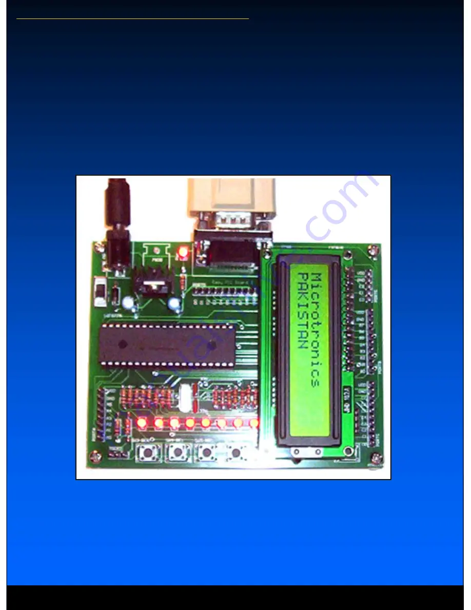
PIC Lab-II Motherboard
User Manual
www.electronicspk.com
Page 1: ...Microtronics Pakistan www electronicspk com PIC Lab II Manual 1 Microtronics Pakistan PIC Lab II Motherboard User Manual Microtronics Pakistan ...
Page 2: ...oad through the board like motor or LEDs etc make sure that the supply current is appropriate In that case we recommend 9V 12V DC adapter 800mA to 1000mA The adapter must have center pin supplying Positive Reverse polarity is checked however There is a blocking diode which will not allow the reverse polarity to reach the board There is an On OFF switch and a Power ON LED indicator The Voltage regu...
Page 3: ... projects We will talk about the related Switch in appropriate topics LED Indicators PORTC 0 PORTC 7 PIC Lab II has 8 Led indicators connected to PORTC of the microcontroller The LEDs are connected through 220 ohms current limiting resistor and are sourced by the microcontroller Therefore a logical 1 or on state of the microcontroller pin will turn the corresponding LED ON DIP Switch 1 will enable...
Page 4: ...he board has however given this a permanent address of 000 The I2C code for EEPROM is 1010 next three bits would be EEPROM chip address and last bit is direction Therefore the complete ad dress to write on EEPROM would be 1010 000 0 and to read it would be 1010 000 1 I2C BUS Connector The board also provides an I2C Bus as a connector which contains connection for SDA and SCL pins along with Power ...
Page 5: ... we talk about 16F877A it has analog inputs on PORTA and E all these pins are available for projects through PORT headers However we have specially included two connectors from PORTA 0 and PORTA 1 along with power supply on board These three pin connectors can be used directly to any analog device giving upto 5V analog signal Pulse Width Modulation Connector PORTC 2 Pulse Width modulation is a com...
Page 6: ...r might use RB3 RB6 and RB7 so your application must not be using them at least at the time of programming the pins should be free By default these pins are free on board If you are connecting an external board just remove the connector Keep the system power on while programming as the programmers can give only small amount of power which is enough for microcontroller but not for the entire board ...
Page 7: ... OUT 9 T1 OUT 14 T2 OUT 7 C1 1 C1 3 C2 4 C2 5 U3 MAX232 C5 10u C6 10u C7 10u C8 10u VDD VDD T2OUT T2OUT R2IN R2IN RC7 RC6 R1IN T1OUT T1OUT 1 2 3 4 5 6 7 8 9 10 J2 PORTB 1 2 3 4 5 6 7 8 9 10 J3 PORTC 1 2 3 4 5 6 7 8 9 10 J4 PORTD RB0 RB1 RB2 RB3 RB4 RB5 RB6 RB7 RC0 RC1 RC2 RC3 RC4 RC5 RC6 RC7 RD0 RD1 RD2 RD3 RD4 RD5 RD6 RD7 VDD VDD VDD 1 2 3 4 5 6 7 8 J5 PORTA 1 2 3 4 5 J6 PORTE RA0 RA1 RA2 RA3 RA4...