background image

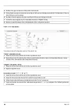
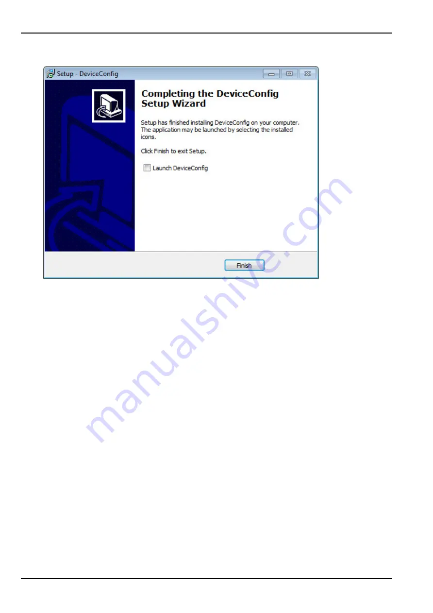
3. Once the following screen is displayed, close the installation process by clicking on the

"Finish"

button.

Complete the setup

11.3.1 Installing the drivers for the USB BLE-Adapter

Note:

Information on the USB BLE-Adapter (300685) is provided in chapter "USB BLE-Adapter " on

page 108.

The following chapter describes the installation process in Windows 7.

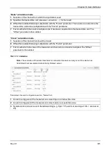
1. Complete all of the steps described in chapter "Installation" on page 102.

2. Close the DeviceConfig configuration program, if, when completing the installation, you selected the

option for the program to be started following completion of the installation process.

3. Connect the USB BLE-Adapter (300685) to a free USB port on your PC. From Windows Vista

onwards, the driver will be installed automatically. Instructions on installing the driver on older versions
of Windows are included in the user manual for the DeviceConfig ("myDatanetDeviceConfig Manual "
805004).

Note:

If possible, always use the same USB port, as the driver will have to be installed for every USB

port used to connect the USB BLE-Adapter (300685) to the PC for the first time.

4. Wait until the driver installation process is complete. This can take several minutes depending on the

performance of your PC.

104

Rev. 01

Summary of Contents for myDatalogGauge 3G

Page 1: ...301134 Rev 01 Cover Valid from l Firmware version 01v018 l App version 02v000 l Server version 47 1 l Hardware version 2 0 User manual myDatalogGauge 3G ...

Page 2: ......

Page 3: ...ht 23 5 3 General descriptive names 23 5 4 Ex protection 23 5 4 1 BLE 3G Gateway ATEX 24 5 4 2 BLE Gauge 24 5 5 Safety instructions 24 5 5 1 Use of the hazard warnings 25 5 5 2 General safety instructions 25 5 5 3 Safety and preventative measures for handling GSM GPRS modems 25 5 5 3 1 Safety and precautionary measures for the GSM GPRS modem installation 26 5 5 3 2 Safety measures for installing t...

Page 4: ...cord module 39 6 2 Functionality of the internal data memory 40 6 3 Procedure in case of connection aborts 41 6 4 Setup mode 41 6 5 Automatic selection of the GSM network 46 6 6 Determining the GSM UMTS LTE signal strength 46 6 7 Determining the position data 46 Chapter 7 Storage delivery and transport 47 7 1 Inspection of incoming deliveries 47 7 2 Scope of supply 47 7 3 Storage 47 7 4 Transport ...

Page 5: ...rgy interface 64 Chapter 9 Initial Start Up 65 9 1 User information 65 9 2 Applicable documents 65 9 3 General principles 65 9 4 Placing the system into operation 65 9 4 1 Using the mobile connection 2G 3G and the myDatanet server 65 9 4 2 Using the Bluetooth connection BLE and the myDatanet server 68 9 5 Testing communication with the device 71 9 5 1 Testing communication between the myDatalogGau...

Page 6: ...ms 91 10 2 1 1 8 Basic settings 92 10 2 1 2 Default input screen for configuring the site 93 10 2 1 2 1 Site 93 10 2 1 2 2 Comments 93 10 2 1 2 3 Alarm settings 94 10 2 1 2 4 Calculated channels 94 10 2 1 2 4 1 Basis 95 10 2 1 2 4 2 Calculation 96 10 2 1 2 4 3 Alarms 97 10 2 1 2 5 Basic settings 98 10 2 2 Device configuration 98 10 2 2 1 Comments 98 10 2 2 2 Measurement instrument 99 10 2 2 3 GPRS...

Page 7: ...th the myDatanet server 115 11 5 7 1 1 Internet connection available when reading out the data 115 11 5 7 1 2 No Internet connection when reading out the data 119 11 6 Functional principle communication with a BLE Gauge sensor module 123 11 6 1 Establishing a connection to a sensor module with Bluetooth Low Energy interface 124 11 6 2 Firmware tab 126 Chapter 12 myDatanet server 127 12 1 Overview ...

Page 8: ...dule specific critical errors 148 16 2 3 Module specific uncritical error 148 16 2 4 Module specific information regarding the current operating state 149 16 3 Evaluating the device log 150 16 3 1 Evaluating the device log on the myDatanet server 150 16 3 2 Evaluating the device log using DeviceConfig 150 Chapter 17 Spare parts and accessories 151 17 1 Assembly sets 151 17 2 Antennas 151 17 3 Sens...

Page 9: ...Chapter 2 Declaration of conformity Chapter 2 Declaration of conformity 2 1 BLE 3G Gateway ATEX Rev 01 9 ...

Page 10: ...2 2 BLE Gauge 10 Rev 01 ...

Page 11: ...Chapter 2 Declaration of conformity Rev 01 11 ...

Page 12: ......

Page 13: ...Chapter 3 Ex certification Chapter 3 Ex certification 3 1 BLE 3G Gateway ATEX Rev 01 13 ...

Page 14: ...14 Rev 01 ...

Page 15: ...Chapter 3 Ex certification Rev 01 15 ...

Page 16: ...16 Rev 01 ...

Page 17: ...Chapter 3 Ex certification 3 2 BLE Gauge Rev 01 17 ...

Page 18: ...18 Rev 01 ...

Page 19: ...Chapter 3 Ex certification Rev 01 19 ...

Page 20: ...20 Rev 01 ...

Page 21: ...0 50 C Air humidity 15 90 rH non condensing Storage and transport temperature 20 70 C Level measurement 2 x BLE Gauge with pressure sensor connected via Bluetooth Low Energy l Applicable regardless of the selected pressure sensor Temperature Resolution suitable for Measurement method 20 50 C 1 0 05 C Fresh waste and grey water Piezoresistive pressure sensor l BLE Gauge pressure sensor 0 1m 9W 3008...

Page 22: ...e Up to 5 years at 10sec measurement interval and 24h transmission cycle 1 The compensation of the temperature related influences on the fill level measurement only occurs in the range of 0 50 C 4 2 BLE Gauge Voltage supply Battery Li SOCl2 cell with 1 2Ah Enclosure Material Weight Degree of protection Dimensions WHD POM Stainless Steel BLE Gauge pressure sensor approx 270g incl pressure sensor an...

Page 23: ... the service area of the myDatanet server 5 1 Translation For deliveries to countries in the European Economic Area the manual must be translated into the language of the respective country If there are any discrepancies in the translated text the original manual German must be referenced or the manufacturer contacted for clarification 5 2 Copyright The copying and distribution of this document as...

Page 24: ...he Ex area l The battery must only be replaced by the manufacturer with certified identical products l Only the manufacturer is permitted to replace the pressure sensor l Only the manufacturer s original spare parts must be used l Due to the electrostatic effects the device must not be rubbed with cloths in the Ex zone l A mounting distance of min 50 mm must be maintained on all sides to prevent a...

Page 25: ... the specifications in the main text 5 5 2 General safety instructions WARNING Never use this device in areas where the use of wireless equipment is prohibited The device must not be used in hospitals and or in the vicinity of medical equipment such as heart pacemakers or hearing aids as their functionality could be compromised by the GSM GPRS modem contained in the device 5 5 3 Safety and prevent...

Page 26: ... to strong vibrations or impacts l The GSM GPRS modem can cause interferences if it is located in the vicinity of television sets radios or computers l Do not open the GSM GPRS modem Any modification to the device is prohibited and will result in the operating licence being revoked l The use of GSM services SMS messages data communication GPRS etc may incur additional costs The user is solely resp...

Page 27: ...5 6 Overview 5 6 1 BLE 3G Gateway ATEX Front of the BLE 3G Gateway ATEX view without protective armour Bottom of the BLE 3G Gateway ATEX view without protective armour 1 Display 3 Activation module BLE ATM 2 Antenna connector Rev 01 27 ...

Page 28: ... Gauge Top of the BLE Gauge Left side of the BLE Gauge incl pressure sensor 1 Pressure compensation 3 Pressure sensor 2 Medium inlet openings 5 6 3 Block diagram Block diagram of the myDatalogGauge 3G 28 Rev 01 ...

Page 29: ...k of the service provider included in the above mentioned list 5 8 General product information The device is a compact battery operated stationary system for recording and transferring fill levels The myDatalogGauge 3G consists of the BLE 3G Gateway ATEX data logger and up to 2 BLE Gauge sensor modules with a pressure sensor for the fill level measurement of fresh waste and grey water Communicatio...

Page 30: ...xt replacement of the batteries of the sensor module The display is either activated via the solenoid switch or by inserting the activation module Detailed information on this is provided in chapter Display on page 76 5 9 Device labelling The information in this user manual applies exclusively to the myDatalogGauge 3G that is made up of the following components l myDatalogGauge IoT app l BLE 3G Ga...

Page 31: ... specifications l Type designation l Serial number l Hardware revision l Item number l Ex protection designation as specified in chapter Declaration of conformity on page 9 l Week and year of production l Environmental conditions during operation l Protection class l Name and address of the manufacturer l Chemical composition of the installed battery l Logo for the EU WEEE Directive l CE marking l...

Page 32: ... use of spare and wear parts that are not approved by the manufacturer shall void the Ex approval 5 11 Storage of the product To store the myDatalogGauge 3G activate transport mode by removing the Activation module BLE ATM from the sensor recess in the device As part of this process a connection to the myDatanet server will first be established so that any data that has not yet been transferred to...

Page 33: ...amages owing to a change of this document The manufacturer reserves the right to change the contents of this document and this disclaimer at any time and without any notice l for damages to persons or objects resulting from failure to comply with applicable regulations For connection commissioning and operation of the devices sensors all available information and higher local legal regulations e g...

Page 34: ...Before commissioning the operator must ensure that the installation and commissioning provided these were performed by the operator himself are in compliance with the local regulations 5 15 Personnel requirements Installation commissioning and maintenance may only be completed by personnel who meet the following conditions l Qualified specialist personnel with the relevant training l Authorised by...

Page 35: ... 1 BLE Gauge incl pressure sensor 2 BLE 3G Gateway ATEX with installed device logic myDatalogGauge and integrated managed service SIM chip 3 USB BLE Adapter Bluetooth Low Energy to USB converter 4 PC with the DeviceConfig configuration program installed 5 myDatanet server to which the data is transferred 6 Smartphone with tbd smartphone app installed 7 Client that accesses the interface of the myD...

Page 36: ... Ex zone 1 used to record fill levels that consists of the BLE 3G Gateway ATEX data logger and up to 2 BLE Gauge incl pressure sensor Communication between the BLE Gauge sensor modules and BLE 3G Gateway ATEX is realised via a Bluetooth connection Bluetooth Low Energy l BLE Gauge incl pressure sensor It is a sensor system approved for Ex zone 1for determining fill levels The transmission of the me...

Page 37: ...onnection Bluetooth Low Energy and transferring it to a central myDatanet server l Managed Service Managed Service is the basis for operating the devices and provides a wide range of services Managed Service includes updates for device firmware mobile data transmission on a global scale and free support providing you with one contact person for the entire solution l myDatanet server Database for s...

Page 38: ...larm trigger module on page 39 3 Adds the value entered via the Sensor Offset configuration parameter to the fill level see Taking the installation height into consideration on page 38 6 Recording of the measurement values see Record module on page 39 6 1 1 Determining the raw value relative pressure The raw value is the relative pressure read directly from the pressure sensor In the range of 0 50...

Page 39: ...nstallation height of the pressure sensor on page 84 6 1 5 Alarm trigger module This module monitors the alarm limits and trigger levels and creates an entry in the alarm list if necessary An immediate transmission is also triggered in the event of a warning or alarm For the measurement channels both the alarm and trigger function of the module are available However only the alarm function is avai...

Page 40: ... this sector again This means that the internal data memory at the very least contains the measurement values of the last 31 633 cycles however at most the measurement values of the last 36 152 cycles For this reason it is recommended to coordinate the transmission cycle and record interval in such a way that a maximum of 31 633 measurement cycles have to be recorded between two transmissions If i...

Page 41: ...n page 130 The myDatalogGauge 3G then terminates the connection to the server again and starts to measure the GSM level for a period of up to 3min During this period the measurement values of the sensors are also recorded to be able to complete a zero point adjustment if required The remaining time until the measurement is terminated is shown on the display of the device and in the Setup data conf...

Page 42: ...white to green Activating setup mode Visualisation of the time for which the reed switch was pressed 1 MDN Magnet 206 803 2 myDatalogGauge 3G The first of the two connections to the myDatanet server are completed as part of setup mode The connection establishment and then the data synchronisation are indicated on the display of the device by means of the relevant graphics Note To check the current...

Page 43: ... until the second connection to the server completed as part of setup mode is shown on the display of the device and in the Setup data configuration section Note You must first open the site settings to access the Setup data configuration section see Site configuration on page 79 Current GSM level and remaining duration of the GSM level measurement Setup data configuration section Setup mode phase...

Page 44: ... to red and the note Setup mode failed enhance antenna position is shown in the Setup data configuration section if a new connection cannot be established within the timeout of 5min In this case setup mode should be activated again once the position of the antenna has been improved Note Information on improving the reception quality is provided in chapter Optimum antenna positioning for assembly i...

Page 45: ... position is shown above the GSM level display Note Information on improving the reception quality is provided in chapter Optimum antenna positioning for assembly in a shaft on page 62 Display of the GSM level determined during setup mode 1 Position of antenna is OK 2 Position of antenna should be improved Note Once terminated the result of setup mode is shown up for a period of 5min on the displa...

Page 46: ...value at a certain time and indicates the average value 2 Average of the data generated during setup mode 6 5 Automatic selection of the GSM network The GSM network to which the device should register must be selected as the myDatalogGauge 3G is equipped with a SIM chip that provides a mobile connection via a variety of international service providers see www microtronics com footprint This is com...

Page 47: ...na see Antennas on page 151 are not part of the standard scope of delivery and must be ordered separately The standard scope of delivery of the myDatalogGauge 3G 300868 includes l myDatalogGauge 3G with pre installed device logic myDatalogGauge l BLE Gateway MDN Protection casing 300662 l MDN Magnet 206 803 l USB BLE Adapter 300685 l Activation module BLE ATM 300962 Check additional accessories de...

Page 48: ...ory for any returns and can be obtained from the Support Service Centre see Contact information on page 157 The return shipment of the myDatalogGauge 3G must occur in the original packaging and with freight and insurance paid to Microtronics Engineering GmbH see Contact information on page 157 Insufficiently cleared return shipments will otherwise not be accepted 48 Rev 01 ...

Page 49: ...is section of the instructions must only be performed by qualified personnel 8 1 Dimensions 8 1 1 myDatalogGauge 3G Dimensions Height view with protective armour Dimensions Width and depth view with protective armour 8 1 2 BLE Gauge and pressure sensor Dimensions BLE Gauge and pressure sensor Length and diameter Rev 01 49 ...

Page 50: ...lected according to specific criteria The following conditions must be avoided in any case l Direct sunlight l Direct influence of weather rain snow l Objects that radiate intense heat maximum ambient temperature 20 50 C l Objects with a strong electromagnetic field frequency converter or similar l Corrosive chemicals or gases l Mechanical impacts l Direct installation on paths or roads l Vibratio...

Page 51: ...nded installations Suspended installation Detailed view of a suspended installation 1 Niro shackle 206 325 2 myDatalogGauge 3G 1 Use the Niro shackle 206 325 to attach the myDatalogGauge 3G to a rung of the channel ladder or a similar fastening point in accordance with the figure Detailed view of a suspended installation on page 51 Rev 01 51 ...

Page 52: ...t be included in the earthing concept of the facility by the installation see Earthing of the BLE Gauge when installed suspended on page 56 The optional BLE Gauge mounting fixture 300881 accessories are required for suspended installations Suspended installation step 1 Suspended installation step 2 1 10x50 wall plug included in the scope of delivery of 300881 4 BLE Gauge 2 6 3x60 Torx 30 rounded h...

Page 53: ...n to the wall see Suspended installation step 1 on page 52 If you are using your own screw you must also insert the wall plug into the hole before screwing the screw on which you want to hang the mounting fixture 3 in to the wall see Suspended installation step 1 on page 52 Once screwed in the distance between the rear of the screw head and the wall should be at least 4mm so that the mounting fixt...

Page 54: ...holder can hold up to 3m of cable Roll up the cable in a clockwise direction Start in such a way that the cable runs from the tension clamp towards the left upper bracket and the circle then continues towards the right upper bracket Important note When rolling up the cable it must be ensured that the bend radius does not fall below the minimum permissible value of 60mm Rolling up the connection ca...

Page 55: ...y be necessary to remove some of the connection cable from the cable holder again Inserting the BLE Gauge BLE Gauge in final mounting position 1 Bracket for theBLE Gauge 2 BLE Gauge 6 Now hang the mounting fixture including the mounted BLE Gauge on the previously prepared screw see Suspended installation step 2 on page 52 The following step is not mandatory 7 Tighten the screw on which the mountin...

Page 56: ...onnection parts for earthing or equipotential bonding conductors l EN60079 11 Chapter 6 5 Earth conductors connections and terminals Earthing of the BLE Gauge when installed suspended 1 Earthing point of the BLE Gauge mounting fixture 3 Earth cable minimum requirement 4mm 2 Earth potential of the facility 4 Earthing pipe clamp 56 Rev 01 ...

Page 57: ... numbers of the BLE Gauge are already saved in the memory of the data logger In this case it suffices to select Automatic mode The saved serial number is displayed in the input field for the serial number although it cannot be changed 3 Enter the installation height of the pressure sensor in the input field for the Sensor Offset parameter see Measurement channels on page 83 4 Ensure that the Trimm...

Page 58: ...l level values with the reference measurement again If the values are still not the same complete the zero point adjustment again Note The current value of the Trimming configuration parameter must now be taken into consideration when calculating the difference between the determined fill level and the reference measurement 8 2 4 2 Zero point adjustment with the help of the Bluetooth connection BL...

Page 59: ... want to take into consideration when calculating the zero point adjustment If necessary you can shorten the record interval for this commissioning phase to reduce the waiting time In this case use the Sync tab of the configuration program DeviceConfig see Sync tab on page 112 to transfer the changed record interval from the site to the myDatalogGauge 3G 9 Trigger the synchronisation between myDat...

Page 60: ...and installation height of the pressure sensor on page 84 14 Trigger the synchronisation between the myDatalogGauge 3G DeviceConfig and myDatanet server again to transmit the changed configuration i e the new Trimming value to the myDatalogGauge 3G and subsequently to the BLE Gauge sensor module 15 If a zero point adjustment was required repeat all of the steps from step 8 Wait until some measurem...

Page 61: ...G is still advisable Storage with the activation module inserted is not recommended due to the significantly increased power consumption when transport mode is deactivated The activation module is inserted in the sensor recess of the myDatalogGauge 3G as illustrated in the following figure It is designed in such a way that it cannot be inserted incorrectly Inserting the activation module 1 Activat...

Page 62: ...to the antenna connector of the myDatalogGauge 3G see Overview on page 27 The following step is not mandatory 2 Check whether the connection to the myDatanet has worked correctly see Testing communication with the device on page 71 8 3 2 1 Optimum antenna positioning for assembly in a shaft 8 3 2 1 1 Typical influences on the signal quality Steel cover up to 30dBm Concrete cover approx 10dBm Envir...

Page 63: ...optimum position of the antenna 1 Install the myDatalogGauge 3G as described in chapter Installing the myDatalogGauge 3G on page 50 During this process also observe the notes regarding the influences on the signal quality see Typical influences on the signal quality on page 62 2 Activate setup mode see Setup mode on page 41 3 Wait until it is indicated in the list of sites applications that the de...

Page 64: ... in chapter Optimum antenna positioning for assembly in a shaft on page 62 Display of the GSM level determined during setup mode 1 Position of antenna is OK 2 Position of antenna should be improved 8 3 3 Technical details about the Bluetooth Low Energy interface The connection to a PC or a Bluetooth Low Energy 4 1 compatible Smartphone is established via the Bluetooth Low Energy interface It is on...

Page 65: ...tire system These instructions are enclosed to the respective additional devices or sensors or are available for download on the Microtronics website 9 3 General principles The entire measurement system may only be placed into operation after completion and inspection of the installation Study the manual thoroughly before placing into operation to prevent faulty or incorrect configuration Utilise ...

Page 66: ... and must be ordered separately 5 To establish a connection activate setup mode see Setup mode on page 41 using the reed switch During this connection the configuration of the site is transferred to the myDatalogGauge 3G Note You can also skip this step as a transmission must also be triggered during installation on site which transfers the configuration settings to the myDatalogGauge 3G at that t...

Page 67: ...d during setup mode 7 Evaluate the result of setup mode If setup mode was completed successfully the determined values for the GSM level are illustrated by the black dots that are connected by a line If the measurement values are not in the green very good or good or yellow OK area we recommend improving the position of the antenna and activating setup mode again If a problem is detected the note ...

Page 68: ...ue is first transmitted to the myDatalogGauge 3G and then to the BLE Gauge sensor module 10 Wait until setup mode is terminated and then compare the determined fill level values with the reference measurement again If the values are still not the same complete the zero point adjustment again Note The current value of the Trimming configuration parameter must now be taken into consideration when ca...

Page 69: ...is set to 0 see Measurement channels on page 83 4 Use the DeviceConfig configuration program to establish a Bluetooth connection Bluetooth Low Energy between the myDatalogGauge 3G and your PC see Establishing a connection to a device with Bluetooth Low Energy interface on page 108 5 Activate the synchronisation between myDatalogGauge 3G DeviceConfig and the myDatanet server To do so initially sele...

Page 70: ... DeviceConfig and the myDatanet server to transmit the recorded fill level measurement values to the myDatanet server 13 Wait until the DeviceConfig configuration program indicates that the synchronisation process is complete Synchronisation completed 14 Click on the Direct Report symbol in the list of sites applications to display the data saved on the myDatanet server 15 A so called report is us...

Page 71: ...tanet server see Creating the site on page 131 2 Configure the created site application according to your requirements see Site configuration on page 79 The following settings should be carried out if you also want to test the communication with the BLE Gauge sensor module at the same time 1 Activate the required measurement channels by selecting the mode and specifying the serial number of the BL...

Page 72: ...e Information on improving the reception quality is provided in chapter Optimum antenna positioning for assembly in a shaft on page 62 Display of the GSM level determined during setup mode 1 Position of antenna is OK 2 Position of antenna should be improved 10 Check whether the values for the fill level determined during setup mode are plausible If necessary complete a zero point adjustment follow...

Page 73: ... Trimming parameter see Measurement channels on page 83 3 Insert the activation module in the sensor recess of the myDatalogGauge 3G see Inserting the activation module on page 61 4 Use the DeviceConfig configuration program to establish a Bluetooth connection Bluetooth Low Energy between the myDatalogGauge 3G and your PC see Establishing a connection to a device with Bluetooth Low Energy interfac...

Page 74: ...tes applications to display the data saved on the myDatanet server 10 Check whether all of the data up to the point of the synchronisation is present and plausible especially the Sensor 1 and or Sensor 2 measurement values Complete a zero point adjustment if the measurement values of the BLE Gauge sensor module do not meet the expectations see Zero point adjustment on page 57 74 Rev 01 ...

Page 75: ...which your responsible sales partner will provide to you 10 1 User interface on the myDatalogGauge 3G 10 1 1 Operating elements Operating elements 1 Reed switch 2 Display 10 1 1 1 Reed switch The MDN Magnet 206 803 included in the scope of delivery is required for operating the reed switch The reed switch can be used to activate setup mode or to switch on the display of the myDatalogGauge 3G for 2...

Page 76: ...splay Important note l Do not touch the display with a sharp object such as the tip of a pen l Do not stand or place any objects on the display as this could scratch it The display of the myDatalogGauge 3G is only designed to show the current measurement values fill level and temperature and various status information The device cannot be operated via the display The display is activated by briefl...

Page 77: ...current fill level in the centre of the display If several BLE Gauge sensor modules are connected to the myDatalogGauge 3G the fill levels of the individual BLE Gauge sensor modules are displayed alternately Based on the currently displayed value the type designation and serial number for the relevant module are shown in the upper section of the display The temperature and remaining days until the...

Page 78: ...nserted Reed switch activated Establishing the BLE connection between BLE Gauge and myDatalogGauge 3G Connecting to the myDatanet server Data synchronisation with the myDatanet server in progress In the event of a connection abort wait until the next connection is established Setup mode the current GSM level and remaining duration of the GSM level measurement Result of setup mode i e the determine...

Page 79: ...ne between BLE Gauge and the pressure sensor interrupted The batteries of the myDatalogGauge 3G need to be replaced 10 2 User interface on the myDatanet server 10 2 1 Site configuration Note Depending on the respective user level some of the configuration fields mentioned in the following sub chapters may be hidden In this case please contact the administrator of the myDatanet server Click on the ...

Page 80: ...lled on the device is displayed in addition to the version number of the site 6 Date when the batteries of the data logger BLE 3G Gateway ATEX are likely to need replacing and remaining days until this date 7 Measurement channel active Type designation of the BLE module currently assigned to the measurement channel and used for measurement value acquisition Measurement channel inactive The string ...

Page 81: ...rement channel is likely to need replacing and remaining days until this date 13 List of tags that are already assigned to the site This assignment can be cancelled by clicking on the cross next to the title of the tag The input screen for assigning tags can be opened by clicking on the plus symbol Site configuration section when transport mode is activated 1 Transport mode activated This means th...

Page 82: ...measured in the last 35 minutes 5 Tool tip that specifies the GSM level at a certain time 6 Visualisation of the GSM level values measured during a single setup mode 7 Visualisation of the fill level of the BLE Gauge assigned to measurement channel 1 measured in the course of a single setup mode 8 Visualisation of the fill level measured in the last 35 minutes measurement channel 1 9 Visualisation...

Page 83: ...acquire the measurement values is assigned manually by entering the serial number of the BLE Gauge in the S N field Off Measurement channel deactivated 3 Serial number of the BLE Gauge used to acquire the measurement values Read Only if automatic mode has been selected for the assignment of the BLE Gauge to the measurement channel 4 Provided to adjust the zero point see Additional explanation on t...

Page 84: ...eration it was determined that the value was 1 cm too high As the Trimming and Sensor offset parameters are added to the measurement value this error can be balanced out by setting the Trimming parameter value to 0 01 m 10 2 1 1 4 2 Alarms Measurement channels configuration section Alarms tab 1 A warning is triggered if the measurement value drops to or below this value 2 A warning is triggered if...

Page 85: ...when the value exceeds or drops below the value in the Threshold field Greater or equal Event trigger RI XM The trigger is initiated if the measurement value meets or exceeds this value Level trigger RA QX The trigger is active as long as the measurement value is higher than the level or equal to the level Less or equal Event trigger RI XM The trigger is initiated if the measurement value drops to...

Page 86: ... device temperature of the myDatalogGauge 3G Air humidity in the housing of the myDatalogGauge 3G GSM level Remaining days until the batteries of the myDatalogGauge 3G need to be replaced Energy consumption between two recordings Sensor status Internal battery voltage of the BLE Gauge Temperature of the pressure sensor of the BLE Gauge Remaining days until the batteries of the BLE Gauge need to be...

Page 87: ...gered if the measurement value meets or exceeds this value 3 An alarm is triggered if the measurement value drops to or below this value 4 An alarm is triggered if the measurement value meets or exceeds this value 5 Hysteresis for all clear in event of alarm warning e g hyst 5 alarm or warning at 100 all clear at 95 6 An alarm is triggered when the battery of the BLE Gauge is depleted Rev 01 87 ...

Page 88: ... must be acknowledged by the user 2 Alarm in case the device does not respond for longer than the set number of transmission cycles An additional tolerance of 10 min is granted per transmission cycle to take any retries when establishing a connection into consideration Example Transmission cycle 60 min 3x transmission cycles Alarm after 03 30 3 Selection of the how the transfer volume alarm should...

Page 89: ...d from which an analogue value is interpreted as high can be selected via the High level parameter in the Calculation tab In addition the determined digital value can be inverted via the Invert parameter x Links the values of two measurement channels using a mathematic operation addition subtraction multiplication or division Delta Determines the difference between two measurement values and divid...

Page 90: ...b 1 Selection of the channel from which the input data is used 2 Opens the screen for entering the reference point table the table rows are interpolated linearly values outside of the defined table are extrapolated linearly Table calculation mode 1 Selection of the channel from which the input data is used 3 Signal recognition level Digital calculation mode 1 Selection of the channel from which th...

Page 91: ...d be cloned 6 Offset that is added following multiplication with the Factor parameter 7 Factor with which the value of the measurement channel to be cloned is multiplied The Offset parameter is then added Clone calculation mode 10 2 1 1 7 3 Alarms Note The evaluation of the alarm thresholds for calculated channels can only occur if the device has transferred the measurement data to the myDatanet s...

Page 92: ... relevant for raw measurement data as this is stored in UTC 6 Configuration for automatic time adjustment Standard The configuration for the time adjustment is adopted by the global server setting siehe myDatanet Server Manual 805002 Off Automatic time adjustment deactivated USA Predefined setting for the American area EU Predefined setting for the European area 7 Position update interval 00 00 po...

Page 93: ...fies to which customer the site is assigned symbol Assign site to another customer Name Site designation not relevant for the device or data assignment 2 50 characters Device S N Serial number of the device that is linked to the site device assignment Application Name of the IoT application based on which the site was created Application version Version number of the IoT application that is curren...

Page 94: ... transfer volume alarm should be triggered can be entered in the adjacent field in KiB Offline alarm after alarm in the event that the device does not report for longer than the set time 00 00 alarm deactivated Title user alarm 1 Freely selectable title for user defined alarm 1 If the user defined alarm 1 is triggered by a device connected to the site the server will use this text to signal the al...

Page 95: ...values The time unit value sec value min for the result can be selected via the Time basis parameter located in the Calculation tab It is thus possible to convert the counter reading m3 of the source in to a flow rate m3 min see Additional explanation Delta mode on page 97 Min Defines the lower scale end of the pointer instruments Max Defines the upper scale end of the pointer instruments Unit Str...

Page 96: ...th which the result of the mathematical operation x is multiplied The Offset parameter is then added Delta Source Selection of the channel from which the input data is used Time basis Specifies the desired time unit value sec value min for the result Offset Offset that is added following multiplication with the Factor parameter The result is converted in to the desired time unit before multiplicat...

Page 97: ...ement at 12 50 for the calculated channels as there is no previous value and the difference between the counter readings cannot be determined For the measurement at 12 51 the difference to the counter reading is 60m3 and the time difference is 60sec Result value difference time difference sec time basis sec factor offset The result for calculated channel 1 time basis Seconds offset 0 and factor 1 ...

Page 98: ...urement data is only displayed in the list of sites applications if a report template has been selected not assigned The symbol to display the measurement data is not displayed in the list of sites applications Name of a report template Name of the report template used to display the measurement data Change log configuration Selection of which changes to the configurations should be logged web api...

Page 99: ...ng the first connection Telephone number Telephone number of the SIM card The control SMS messages e g wakeup are sent to this number Format 43555837465 Instrument flags Additional information regarding the instrument class for internal use Firmware version Current software version installed on the measurement controller Modem version Current software version installed on the modem controller OS v...

Page 100: ...he firmware update is deactivated and no information is provided about available firmware updates Firmware type Released Only firmware versions that have successfully undergone internal and field testing are installed this practically eliminates malfunctions Release candidate Only firmware versions that have successfully undergone internal testing are installed malfunctions cannot be excluded Beta...

Page 101: ...lly adjusts to the relevant device that is connected In addition to the standard functions the tool also supports device specific processes e g calibration zero point adjustment The DeviceConfig enables you to complete the following tasks l Synchronisation of measurement data and configuration between device and server specifically for devices without GSM GPRS modem l Basic configuration of the de...

Page 102: ... 7 1 Execute the InstDeviceConfig exe file to start the installation process Note Only connect the device or USB BLE Adapter 300685 to your PC once the installation process has completed as the required drivers are only installed during this process DeviceConfig setup wizard 102 Rev 01 ...

Page 103: ...wing drivers must be installed to ensure correct operation Installation of the USB drivers for the devices Installation of the drivers for the USB BLE Adapter Installation of the USB drivers for the devices on a M1 basis Installation of the USB drivers for the devices on a M2 M3 basis Rev 01 103 ...

Page 104: ... selected the option for the program to be started following completion of the installation process 3 Connect the USB BLE Adapter 300685 to a free USB port on your PC From Windows Vista onwards the driver will be installed automatically Instructions on installing the driver on older versions of Windows are included in the user manual for the DeviceConfig myDatanetDeviceConfig Manual 805004 Note If...

Page 105: ...e firmware versions can be activated or deactivated via the Settings Options menu item The USB radio transmitter 206 657 is required for myDatanet devices that are connected to the PC via a wireless M bus while the USB BLE Adapter 300685 is required for devices that are connected to the PC via Bluetooth Low Energy Information on whether your device supports one of these connection methods is provi...

Page 106: ...dio transmitter 206 657 only visible when the automatic search is deactivated 2 Activates deactivates the automatic search for the USB BLE Adapter 300685 on all of the available COM ports 5 COM port that is connected with the USB BLE Adapter 300685 only visible when the automatic search is deactivated 3 Activates deactivates the automatic search for available firmware versions 106 Rev 01 ...

Page 107: ... communicates wirelessly Bluetooth Low Energy with the myDatalogGauge 3G using the USB BLE Adapter 300685 The functions provided with the DeviceConfig configuration program include l Read out and analysis of the device log see Log tab on page 110 l Update the firmware see Firmware tab on page 112 l Synchronisation of measurement data and configuration between device and server see Sync tab on page...

Page 108: ...up to 180 cm is possible without any problems 11 5 2 Establishing a connection to a device with Bluetooth Low Energy interface The USB BLE Adapter 300685 is required to establish a connection to a device with a Bluetooth Low Energy interface First of all complete the steps described in chapter Installing the drivers for the USB BLE Adapter on page 104 to install the drivers required to operate the...

Page 109: ... device additional tabs may be displayed Sync tab when actively connected to the myDatalogGauge 3G 1 Wireless signal level dBm Note To ensure a stable connection the wireless signal level should be higher than 90dBm i e for example 85dBm This is achieved by reducing the distance between the myDatalogGauge 3G and and avoiding obstacles such as walls and similar 11 5 3 GSM tab This tab can be used t...

Page 110: ... the log entries from the memory of the device 2 Time stamp of the log entry 6 Loads the log entries from the device 3 Log entry 7 Saves the loaded log entries as a tsv file 4 Parameter of the log entry 8 Window to display the loaded log entries The coloured highlighting indicates how crucial the log entry is The white informative log entries are only displayed when the detailed display of the log...

Page 111: ...t blue Blue Purple Grey Yellow Uncritical error Red Critical error Log tab with detailed view activated 1 Activates the detailed display of the log entries 3 Log entry that is always displayed 2 Informative log entry that is only visible if the detailed display is activated Rev 01 111 ...

Page 112: ... 3 The firmware is loaded directly from the server and installed on the device 2 Button to install a previously downloaded firmware package 11 5 6 Sync tab This area is designed to synchronise measurement data and configurations between myDatalogGauge 3G DeviceConfig and myDatanet server The Sync tab is also available if there is no connection USB wireless M bus or Bluetooth to a device Detailed i...

Page 113: ...onfigurations of the myDatalogGauge 3G with the DeviceConfig configuration program As soon as your PC establishes a connection to the Internet for example when you return to the office you can then complete the synchronisations between the DeviceConfig and myDatanet server see No connection to a device on page 114 Sync tab when connected to the myDatalogGauge 3G 1 Checkbox to determine whether the...

Page 114: ...ile reading out the measurement data and configurations from the myDatalogGauge 3G Sync tab without connection to a device 1 Button to trigger synchronisation During this process the measurement data and configurations for all of the devices that the DeviceConfig configuration program has saved locally are synchronised with the myDatanet server 114 Rev 01 ...

Page 115: ...hronise the data with the DeviceConfig configuration program but also with the myDatanet server A site must already be assigned to the myDatalogGauge 3G on the myDatanet server for this purpose Detailed instructions are provided in chapter Creating the site on page 131 Another prerequisite for this is that your PC is connected to the Internet while reading out the data from the myDatalogGauge 3G I...

Page 116: ... is only visible if your PC is currently connected to the Internet Sync tab when connected to the myDatalogGauge 3G 1 Checkbox to determine whether the measurement data and configurations should also be synchronised with the server when clicking on the Sync button Note This checkbox is only displayed if your PC is already connected to the Internet 2 Button to trigger synchronisation 116 Rev 01 ...

Page 117: ... of the saved data can take several hours depending on the number of saved measurement data records 2 Only read out the data from the selected date onwards The data is always read out from 00 00 am of the selected day Important note Following completion of the synchronisation it is no longer possible to read out data before the selected date If the DeviceConfig configuration program determines tha...

Page 118: ...he option to select from which time period onwards the data should be read out opens The measurement data is read out from the myDatalogGauge 3G in accordance with the selection and assigned to the new site 2 The locally saved data is assigned to the new site from the selected point in time onwards 3 All locally saved data is assigned to the new site 7 Wait until the DeviceConfig configuration pro...

Page 119: ...n Internet connection cannot be established on the site while reading out the data from the myDatalogGauge 3G During this procedure the data on the site is initially only synchronised with the DeviceConfig configuration program The data is then transferred to the myDatanet server at a later date when your PC has re established a connection to the Internet 1 Connect the USB BLE Adapter 300685 to th...

Page 120: ...hronisation When you read out the data for the first time from a myDatalogGauge 3G you can choose whether all of the saved data or only the data up to a certain date are read out from the myDatalogGauge 3G During the following synchronisation processes the DeviceConfig configuration program always reads out the data from the last synchronised measurement data record 120 Rev 01 ...

Page 121: ...ted date onwards The data is always read out from 00 00 am of the selected day Important note Following completion of the synchronisation it is no longer possible to read out data before the selected date 6 Wait until the DeviceConfig configuration program indicates that the synchronisation process is complete Synchronisation completed 7 Close the DeviceConfig configuration program 8 Re open the D...

Page 122: ...onisation During this process the measurement data and configurations of all of the devices that the DeviceConfig configuration program has saved locally are synchronised with the myDatanet server 10 Wait until the DeviceConfig configuration program indicates that the synchronisation process is complete Synchronisation completed 122 Rev 01 ...

Page 123: ...ule Functional principle 1 BLE Gauge sensor module 3 PC with the DeviceConfig configuration program installed 2 USB BLE Adapter The DeviceConfig configuration program communicates wirelessly Bluetooth Low Energy with the BLE Gauge sensor module using the USB BLE Adapter 300685 The functions provided with the DeviceConfig configuration program include l Update the firmware see Firmware tab on page ...

Page 124: ... drivers for the USB BLE Adapter on page 104 to install the drivers required to operate the USB BLE Adapter 1 Connect the USB BLE Adapter 300685 to the USB interface of your PC 2 Start the DeviceConfig configuration program DeviceConfig 3 Select your sensor module based on the serial number from the list of devices found Important note Sensor modules that are successfully coupled with a myDatalogG...

Page 125: ...nstrument tab when actively connected to the sensor module 1 Radio signal strength dBm Note To ensure a stable connection the wireless signal level should be higher than 90dBm i e for example 85dBm This is achieved by reducing the distance between the sensor module and the USB BLE Adapter and avoiding obstacles such as walls and similar Rev 01 125 ...

Page 126: ...tab This tab enables firmware to be installed directly via the Bluetooth Low Energy interface Firmware tab 1 Currently installed software version 2 Button to install a previously downloaded firmware package 126 Rev 01 ...

Page 127: ...Opens the rapidM2M Playground 3 Displays the menu for adjusting the user settings and for logging out the currently active user 7 Switches to the Data exports area to configure the data export This tab is only visible if at least the licence for one export variant is available 4 Tabs to switch between the individual server areas 8 Opens the input screen to upload a XML file This tab is only visibl...

Page 128: ...can be displayed as a Map and or the OpenStreetMaps map can be displayed The sites can be manually placed on the image file used as a map In the OpenStreetMaps map the sites are only displayed once GPS coordinates have been assigned to the site 2 Adds a new customer 128 Rev 01 ...

Page 129: ...hidden the selected tag is highlighted in colour and the title of the tag is crossed out Clicking the same mouse button again will remove the restriction 4 Opens the input screen for configuring the customer 5 Deletes the customer 6 Comment that can be entered in the configuration of the customer 7 If a default report was defined the default report is accessed by clicking on the name of the custom...

Page 130: ...a Map and or the OpenStreetMaps map can be displayed The sites can be manually placed on the image file used as a map In the OpenStreetMaps map the sites are only displayed once GPS coordinates have been assigned to the site 2 List of reports see Reports on page 131 3 List of sites applications see Site on page 93 130 Rev 01 ...

Page 131: ... on creating and handling the reports is provided in myDatanet Server Manual 805002 12 3 2 Map view The map view provides an overview of the geographic position of the sites Detailed instructions on operating and configuring map view are provided in myDatanet Server Manual 805002 12 4 Recommended procedure 12 4 1 Creating the site Note Some of the fields mentioned in the following chapters may be ...

Page 132: ...all up the list of existing sites applications Open the input window for creating a new site by clicking the Add new site application symbol enter the serial number of your device in the appropriate field and then click the Continue button Note The serial number is on the type plate of the device see Device labelling on page 30 Creating the site 1 Menu item to call up the list of existing sites ap...

Page 133: ... the site select the desired site type or the desired application from the drop down list and then click the Add button Completing site creation 1 Name of the site freely selectable 3 Add button 2 Drop down list of available applications templates and site types Rev 01 133 ...

Page 134: ......

Page 135: ...ut includes all of the data provided by myDatanet server e g configurations It is therefore possible for the customer to completely dispense with the interface of the myDatanet server and to create his own user interface A specially developed PC program or web interface can for example be used for this purpose 13 2 rapidM2M Playground The rapidM2M Playground enables you to familiarise yourself wit...

Page 136: ...ditional information for developers 7 Opens the quick guide for the API 8 Button for displaying the menu that contains the global settings 9 Button to change the colour scheme of the rapidM2M Playground 10 Window displaying the selected HTTP command 11 Response code sent by the myDatanet server as an answer to the HTTP command 12 Copies the JSON object generated as a response to the HTTP command o...

Page 137: ...ce work which must also be completed strictly outside the Ex area The myDatalogGauge 3G itself does not require any cyclic maintenance work other than the actions listed in chapter General maintenance on page 137 and replacement of the batteries after max 5 years In the event of unfavourable environmental conditions e g low temperatures it may occur that the battery capacity is depleted before thi...

Page 138: ...remaining number of days until the battery of the BLE Gauge must be replaced is shown on the display of the myDatalogGauge 3G see Display on page 76 138 Rev 01 ...

Page 139: ...t be observed Microtronics Engineering GmbHsupports and promotes recycling and environmentally friendly separate collection disposal of waste from electric and electronic equipment in order to protect the environment and human health Observe the local laws and regulations on disposal of electronic waste at all times Microtronics Engineering GmbHreleases goods brought onto the market in Austria fro...

Page 140: ......

Page 141: ...e device log from the myDatalogGauge 3G or the myDatanet server and use DeviceConfig for the report see Evaluating the device log on page 150 l The capacity of the battery pack is virtually depleted Not all or no data is available on the server l The measurement data and configurations have not been synchronised between the DeviceConfig configuration program and the myDatanet server l The connecti...

Page 142: ...not detected l Increase the record interval attention This will increase the required data volume Alarm state was not transferred although the data is present l Check the alarm settings of the measurement channel l The connection was aborted during the transmission which is indicated by a time out entry in the connection list see myDatanet Server Manual 805002 Solution Activate setup mode or wait ...

Page 143: ...R The rechargeable battery or battery voltage once again suffices to guarantee reliable operation This is achieved by replacing the rechargeable battery or battery pack The device resumes normal operation in accordance with the configuration 1034 CONTROLLER UPDATE Controller firmware update was completed successfully This entry is always duplicated in the device log In the first entry the paramete...

Page 144: ...arameter specifies the type of error 1203 SELECTED NETWORK A new GSM network was selected This entry is always duplicated in the device log In the first entry the parameter specifies the MCC Mobile Country Code while in the second entry it specifies the MNC Mobile Network Code of the selected GSM network 1212 ERROR MODEM IRREGULAR OFF Indicates a faulty connection The parameter includes a counter ...

Page 145: ... DISCARDED SIM state was changed to DISCARDED device has been decommissioned 2000 2199 MODULE ERR Module specific critical error see Module specific critical errors on page 148 2200 2399 MODULE WARNING Module specific uncritical error see Module specific uncritical error on page 148 2400 2599 MODULE INFO Module specific information about the current operating state see Module specific information ...

Page 146: ...rove the position of the antenna l Check whether the device is in the coverage area www microtronics com footprint 1200 BAND SEL FAILED 969 A network could not be found on the GSM900 1800 or on the GSM850 1900 band l Try to improve the position of the antenna l Check whether the device is in the coverage area www microtronics com footprint 146 Rev 01 ...

Page 147: ...ailable Try again later TCP DNS FAILURE 958 The name could not be resolved in an IP address Internal error CHANNEL REFUSED 955 The TCP connection has been refused by the server Try again later CHANNEL HOST UNREACHABLE 954 No route to the host Try again later CHANNEL NETWORK UNREACHABLE 953 No network available Try again later CHANNEL PIPE BROKEN 952 TCP connection interrupted Try again later CHANN...

Page 148: ...rror several times see Contact information on page 157 16 2 3 Module specific uncritical error Log entry Parameter Description Code Plain text Code Plain text 2200 Service interval gateway 0 The batteries of the myDatalogGauge 3G need to be replaced 2201 Service interval sensor 1 Battery of the BLE Gauge that is assigned to measurement channel 1 needs to be replaced 2 Battery of the BLE Gauge that...

Page 149: ...of the BLE Gauge that is assigned to measurement channel 1 This entry is always duplicated in the device log In the first entry the parameter specifies the higher 16Bit of the serial number and the second entry specifies the lower 16Bit of the serial number 2410 Solenoid switch was released again after being pressed 0 Solenoid switch was released again after being pressed Solenoid switch pressed 1...

Page 150: ... device list As the log entries are sent to the server in the transmission cycle in the same way as the measurement data only the log entries up to the last server connection are available The manual for the server myDatanet Server Manual 805002 includes a detailed description of the evaluation of the device log on the myDatanet server 16 3 2 Evaluating the device log using DeviceConfig The Device...

Page 151: ...s Note The required pressure sensor with the relevant measurement range must be specified when ordering the BLE Gauge The pressure sensor cannot be replaced by the user Description Measurement range Quantity Order number BLE Gauge pressure sensor 0 3m 9W 0 3m 1 300871 BLE Gauge pressure sensor 0 1m 9W 0 1m 1 300872 BLE Gauge pressure sensor 0 10m 9W 0 10m 1 300891 17 5 Other accessories Descriptio...

Page 152: ......

Page 153: ...Chapter 18 Document history Chapter 18 Document history Rev Date Changes 01 16 04 2021 First version Rev 01 153 ...

Page 154: ......

Page 155: ...on e g rapidM2M M2 HW1 4 The part of the hardware ID string that specifies the hardware version is only increased if changes relevant to the rapidM2M firmware have been made to the hardware platform When developing an app model it can be specified on which hardware platform the app model can be installed and which version of the hardware platform is required as a minimum The hardware ID string is ...

Page 156: ...l via the rapidM2M Studio rapidM2M timestamp Depending on the required accuracy one of two special encodings can be used for the time stamp in rapidM2M If the accuracy requirements are moderate the stamp32 data type seconds since 1999 12 31 00 00 00 UTC can be used If a higher accuracy is required the stamp40 data type 1 256 seconds since 1999 12 31 00 00 00 UTC can be used Converting the stamp32 ...

Page 157: ... Hauptstrasse 7 3244 Ruprechtshofen Austria Europe Tel 43 0 2756 7718023 support microtronics com www microtronics com Microtronics Engineering GmbH Headquarters Hauptstrasse 7 3244 Ruprechtshofen Austria Europe Tel 43 0 2756 77180 Fax 43 0 2756 7718033 office microtronics com www microtronics com Rev 01 157 ...

Page 158: ...01 2011 for myDatanet TÜV SÜD ATEX Directive 2014 34 EU Microtronics Engineering GmbH All rights reserved Photos Microtronics 301134 Rev 01 Microtronics Engineering GmbH www microtronics com Hauptstrasse 7 3244 Ruprechtshofen Austria 43 2756 77180 office microtronics com ...

Reviews: