


Chapter 7 Installation
The 120Ω load resistance between RS485 A and B can be activated via the "RS485_Init()" function.
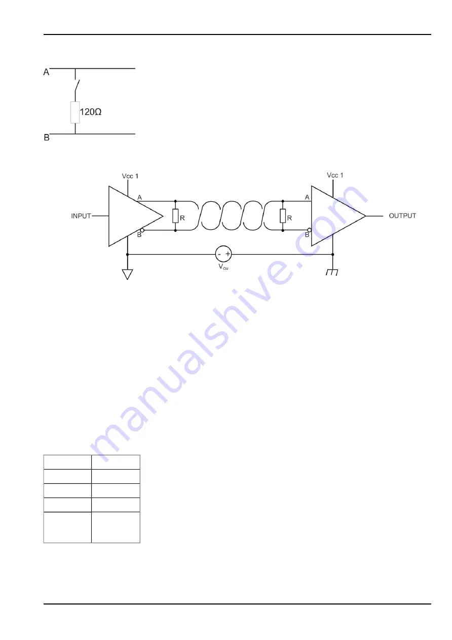
Schematic diagram of the switchable load resistance
Note:
Additional explanation regarding the connection of two RS485 bus participants
Schematic diagram: Connection of two RS485 bus participants
A problem occurs if there is no connection between the GND potentials of the sender and recipient. A common
mode voltage (V
CM
) occurs in this case. The GND potential difference must not exceed max. +/- 7V . Higher
voltages will damage the interface. Temporary overvoltages (ESD, EFT and surge) are, however, absorbed by
protective circuits.
Note: The common mode input voltage range of -7V...+12V specified for the RS485 is determined from the
max. permissible GND potential difference (+/- 7V ) and the max. permissible output voltage range of 0...5 V for
RS485.
7.5.6 Technical details about the RS232 interface
Note:
The RS232 interface of the myDatalogEASY IoTmini is compatible with standard TIA/EIA-
232-F.
The output drivers are protected against overloading and are not damaged by a short circuit to the GND or +/-
15 V. The inputs are equipped with a 5 kΩ load resistance.
Baud rate
600-115200
Stop bits
1, 2
Parity
N, E, O
Data bits
7, 8
Flow control Off
RTS/CTS
The direction of the signals corresponds to that of a DTE (e.g. PC).
Rev. 01
57