background image

24

X22-19688-01

Step 5: Non-Skid Foot Pad Installation Process

Procedure - Installation (Non-Skid Food Pad) 

IMPORTANT:

 Do not reuse feet previously removed from a device unless device will be returned for 

exchange. New feet must be used or the adhesive on the feet will not properly adhere to the device.

1.  Prepare new front feet and press into place - To reassemble front foot, remove protective sheet to expose 

adhesive on foot. Align the 3 posts with their respective pockets on the bottom side of the unit and hand 

press the foot in until the foot sits flat. Complete previous steps for the other front foot.

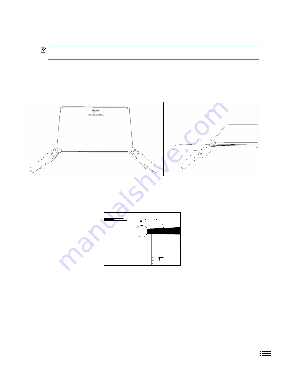
2.  Clamp replaced feet - Align and center the press head of the clamp onto the front feet. Clamp both of the 

front feet and allow to remain for 4 minutes before releasing the clamp.. 

3.  Inspect for anomalies - Inspect feet after removing clamps to ensure no cosmetic damage or gaps  

between the foot and the chassis exist

a.  If gap exists, use a feeler gage to check if the gap is smaller than 0.050 mm. If gap is larger,  

replace foot

4.  Prepare new back feet and press into place - To reassemble the back feet, remove protective sheet to 

expose adhesive on foot. Insert the foot into the pocket on the bottom side of the unit and hand press the 

foot in until the foot sits flat

5.  Clamp replaced feet - Align and center the press head of the clamp onto the back feet. Clamp both the 

back feet down and allow to remain for 4 minutes before releasing the clamp.

6.  Cosmetic Inspection - Inspect feet after removing clamps to ensure no cosmetic damage or gaps exist

Summary of Contents for Surface 3 Pro

Page 1: ...rSSD Removal Guide for Enterprise X22 19688 01 ...

Page 2: ...fitness for a particular purpose To the fullest extent permissible by law Microsoft shall not be liable for damages of any kind arising from the use of information content materials or product made available in or in conjunction with this Manual including but not limited to direct indirect incidental consequential and or punitive damages unless otherwise specified in writing Notice Microsoft and i...

Page 3: ...T PROCEDURES 11 PRIOR TO DEVICE DISASSEMBLY 11 CURRENT BATTERY WARNING 11 STEP 1 NON SKID FOOD PAD REMOVAL PROCESS 12 STEP 2 DEVICE C COVER KEYBOARD REMOVAL 13 PROCEDURE REMOVAL PROCESS C COVER KEYBOARD METAL TYPE 14 PROCEDURE REMOVAL PROCESS C COVER KEYBOARD FABRIC TYPE 16 STEP 3 RSSD REPLACEMENT PROCESS 19 PROCEDURE REMOVAL RSSD 20 PROCEDURE INSTALLATION RSSD 20 STEP 4 DEVICE C COVER KEYBOARD AS...

Page 4: ... cover Item 2 in Illustrated Service Parts list Removable Solid State Drive is referred to as rSSD Item 3 in Illustrated Service Parts list BMR refers to the imaging process and stands for Bare Metal Recovery Device bottom case is referred to as chassis or D chassis or D bucket Surface Diagnostic Toolkit is referred to as SDT Electro Static Discharge is referenced as ESD Flexible Printed Circuits ...

Page 5: ... 15 Standard Service Tools Anti static wrist strap 1 MOhm resistance Spudger tool Torx plus screwdriver 5IP Isopropyl alcohol IPA 99 Isopropyl alcohol dispense bottle Cleaning swabs ESD safe tweezers Heavy duty suction cups 2 2 25 Plastic feeler gauge 0 50mm Clamps 2 2 spring The tools identified on this list can be purchased from many different commercial sources including but not limited to Amaz...

Page 6: ...ded by a standard mains wall outlet Do not use non standard power sources such as generators or inverters even if the voltage and frequency appear acceptable Improper use of device batteries may result in fire or explosion Only open the enclosure on a device as outlined in this manual Do not heat puncture mutilate or dispose of devices or their batteries in fire Do not leave or charge devices in d...

Page 7: ...vities Refer to Prior to Device Disassembly section page 11 for details If battery damage e g leaking expansion folds or other is discovered during the rSSD removal process or if the battery is impacted or damaged during the removal process activities should cease Refer to Microsoft Operational guidelines or contact Microsoft directly for proper device disposition As you remove each subassembly fr...

Page 8: ...t are included with the Microsoft device such as power supplies keyboards mice cables charging connectors etc 4 Any devices that exhibit a case that has separated apart or opened for reasons other than customer abuse e g impact damage from dropping evidence of tampering separation caused by a malfunctioning battery 5 Any other finding that may constitute a safety hazard to the customer such as sha...

Page 9: ...omponent Part No 1867 1868 1872 1873 1 Non Skid Foot Pad Feet WW Hdwr Black FRU Exchange RPW 00001 X X X Feet WW Hdwr COBALT BLUE FRU Exchange RPW 00002 X Feet WW Hdwr Platinum FRU Exchange RPW 00003 X X X Feet WW Hdwr Sandstone FRU Exchange RPW 00004 X 1 2 3 ...

Page 10: ...Troubleshooting Approach The following approach should be considered when troubleshooting Surface devices 1 Update device to latest OS FW versions using the SDT tool IMPORTANT This is a must do prerequisite to all hardware repairs 2 Verify any suspected hardware failures by setting the device in a known OS FW version state and running SDT to verify fault a Replace the device s internal rSSD with a...

Page 11: ... activities CAUTION Check C cover and device enclosure for any loose articles that may be present inadvertently on the C cover or within the device enclosure IMPORTANT Once the rSSD has been removed powering on the device requires that the rSSD and C cover FRUs are installed and device must be connected to a power supply Refer to Procedure Removal rSSD section page 20 for details IMPORTANT Once th...

Page 12: ...There are two types of feet front and back refer to illustration for details Procedure Removal Non Skid Foot Pad 1 Front foot removal technique To remove front feet insert the pointed end of a plastic Spudger tool pictured from the long side of the device under the foot There is a designed gap in the foot located at the center of the outside edge of the foot Point the plastic tool directly in the ...

Page 13: ...s o 5IP Torx Plus driver o Anti static wrist strap 1M Ohm resistance o Recommended ESD safe Battery Cover 13 5 or 15 Components o New 5IP screw qty 4 o C cover If replacing Prerequisite Steps Power off device Ensure device is powered off and disconnected from a power supply General Safety Check to make sure that general guidelines and ESD compliance steps are followed prior to opening device Refer...

Page 14: ... and hold in a hover position as described below to avoid damaging the display glass Never rest the rear edge of the C cover on the device at the display hinge point or allow the C cover to impact or touch the display during this step IMPORTANT In addition to the 4 C cover screws the C cover is further secured to the device body with magnets Further separation of the C cover should be carried out ...

Page 15: ...uring storage WARNING It is recommended that an ESD safe battery cover of appropriate size either 13 5 or 15 device be placed across the device to protect the battery from any physical contact or accidental damage whenever C cover is removed Ensure corners of cover are aligned with the corners of the device at all times while battery is exposed If battery cover is misaligned during activities in a...

Page 16: ...re Removal C cover Keyboard Fabric Type 1 Remove C cover screws Using a 5IP Torx Plus driver uninstall 1 screw from each foot socket 4 CAUTION The fabric type C cover needs to be disassembled through a different process than for metal type C covers This is because fabric C covers have a hook latching onto the chassis whereas metal C covers do not See illustration for details IMPORTANT Take caution...

Page 17: ...te C cover from device Once C cover separation from the device bottom case is achieved place a finger between the C cover and device region and pull upwards slightly to separate the C cover from the magnets 4 Angle C cover Angle the C cover at approximately 45 degrees from horizonal be sure to angle the C cover no more than 45 degrees or else risk damaging the C cover hook or FPC If hook is damage...

Page 18: ...from cosmetic damage during storage WARNING It is recommended that an ESD safe battery cover of appropriate size either 13 5 or 15 device be placed across the device to protect the battery from any physical contact or accidental damage whenever C cover is removed Ensure corners of cover are aligned with the corners of the device at all times while battery is exposed If battery cover is misaligned ...

Page 19: ... details Remove feet Follow steps for Procedure Removal Non Skid Foot Pad section page 12 prior to C cover removal IMPORTANT Be sure that all foot adhesive remains have been removed from the bottom device case foot sockets prior to C cover screw removal to avoid the risk of stripping out the C cover screw s Remove C cover Follow steps for Device C cover Keyboard Removal fabric or metal type sectio...

Page 20: ...nstallation rSSD If an rSSD is being replaced in the device follow the steps in this section otherwise skip to the next section for re assembly of device prior to return to Microsoft IMPORTANT Only a Microsoft rSSD with part number as specified in the parts list by device model and of like capacity should be replaced in the device 1 Insert rSSD Insert the connector end of the rSSD into the rSSD co...

Page 21: ...ng on the device requires that the rSSD and C cover FRUs are installed and device must be connected to a power supply Refer to Procedure Installation rSSD section page 23 for details 5 Run SDT Run SDT to ensure all device features and functions operate as expected 6 Install feet If SDT tests pass and no further actions are to be performed on the device follow steps for Procedure Installation Non S...

Page 22: ...o folds or creases are created during re assembly of C cover 4 Align the C cover Properly align the cover to the unit using the front edge alignment posts Carefully place the C cover back onto the unit and shift until the C cover snaps into place CAUTION Ensure that the C cover is correctly aligned and seated before closing the device There is the risk of breaking the display if the device lid is ...

Page 23: ... cover to the unit using the front edge alignment posts Carefully place the C cover back onto the unit and shift until the C cover snaps into place CAUTION Ensure that the C cover is correctly aligned and seated before closing the device There is the risk of breaking the display if the device lid is closed before C cover is aligned 5 Install C cover Screws Turn the unit over and use a 5IP screwdri...

Page 24: ...nto the front feet Clamp both of the front feet and allow to remain for 4 minutes before releasing the clamp 3 Inspect for anomalies Inspect feet after removing clamps to ensure no cosmetic damage or gaps between the foot and the chassis exist a If gap exists use a feeler gage to check if the gap is smaller than 0 050 mm If gap is larger replace foot 4 Prepare new back feet and press into place To...

Page 25: ... ms surface regulatory or in the Surface app All waste materials including waste electrical and electronic and electric equipment WEEE and batteries must be managed according to applicable laws and regulations and Microsoft standards and requirements including H09117 Available for download at Link In case of questions please contact AskECT microsoft com ...

Reviews: