

Introduction
This unmanaged 5-port Gigabit Ethernet desktop switch
is ideal to build high-performance switched workgroup
networks.
The device has four 10/100/1000Base-T (RJ-45) ports
and one SFP slot according to 1000Base-X. The RJ-45
ports support auto-crossing and auto-negotiation. All
ports are supporting full Gigabit speed and are
configured automatically.
Features
Compact, cost effective, fan less Gigabit Ethernet switch
4x 10/1000/1000Base-T + 1x 1000Base-X SFP slot
Store-and-forward architecture
4K MAC addresses
Flow Control and Back-pressure acc. IEEE802.3x
Auto-negotiation for all RJ-45 ports
Automatic identification of MDI/MDI-X auto-crossing
2M buffer memory built in chip
External power adapter
Packing list
Please check the following items in the package before
installing the switch.
5-port Gigabit Ethernet Switch
1 pc.
AC/DC adapter (external)
1 pc.
Rubber pads
4 pcs.
User manual
1 pc.
Please contact your reseller immediately for any loss or
damage to the above items.
Installation
RJ-45 Interface
The RJ-45 ports support min. CAT 5 twisted-pair cables
with a maximum length of 100 meter. A configuration of
the RJ-45 interface is not necessary. Due to the
auto-negotiation feature, port speed (10/100/1000 Mbps)
and duplex mode (full or half-duplex) are set
automatically. Furthermore, auto-crossing is supported;
this means that crossed or straight patch cords can be
used independent on the opposite RJ-45 port.
Fiber interface
The SFP slot supports Gigabit Ethernet transceivers.
MICROSENS offers several suited single mode or
multimode transceivers for different distances.
Power interface
The 5 VDC power socket is located at the rear panel side.
A suitable AC/DC power adapter with EURO connector
is included in the delivery. Other power connectors are
available on request.
Connection
Insert the SFP transceiver into the SFP slot. Ensure that
the SFP type matches to the fiber type, distance and
transceiver at the remote side. Connect the device to the
external power supply. Now plug the fiber connectors
into the SFP transceiver.
After that, all network devices with copper interfaces can
be connected to the RJ-45 ports. Observe the
corresponding Link LED in order to ensure that the link
is established correct.
The speed of the TP-link is indicated by the TP Speed
LED. Check that the maximum speed supported by the
end device is shown by the LED. If this is not the case,
please configure the end device manually to the
maximum speed.
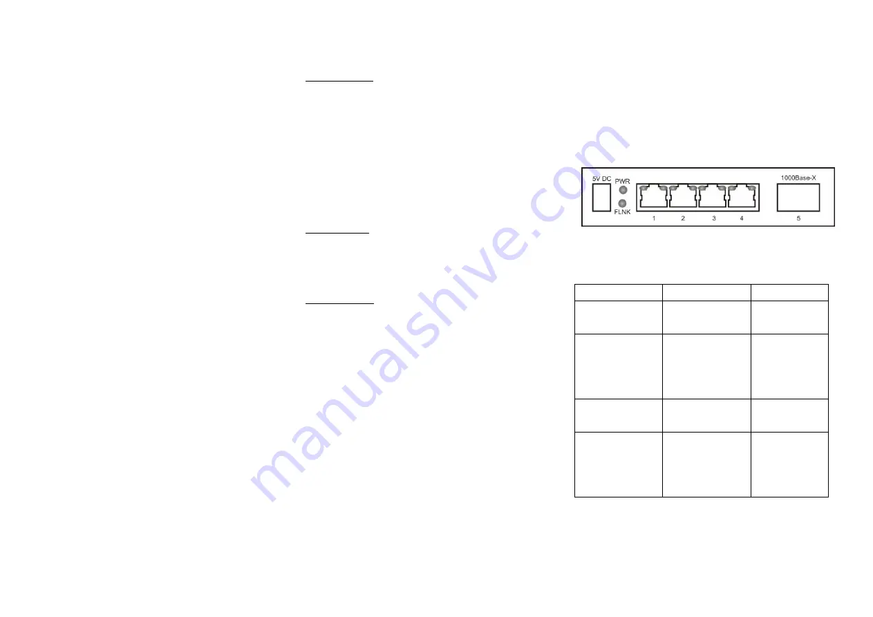
Figure 1: Rear panel view
LEDs
LED
On
Off
PWR
(green)
Power supply
is ok
Power supply
has failed
FLNK
(green)
Fiber is
connected
flashing for data
transmission
Fiber isn't
connected
TP Speed
(left one/amber)
1000M
10M or 100M
TP Link
(right one/green)
Network is
connected
flashing for data
transmission
Network isn't
connected


