background image

Microsemi Proprietary and Confidential. LX3301A/LX3302A Auto Calibration User Guide Revision 1.0

14

4.2

Example Data and EEPROM Parameters Loaded

The following image shows an example of loaded data and EEPROM parameters.

Figure 23 • Example Loaded Data and EEProm Para Loaded

4.3

Calibration Condition Settings

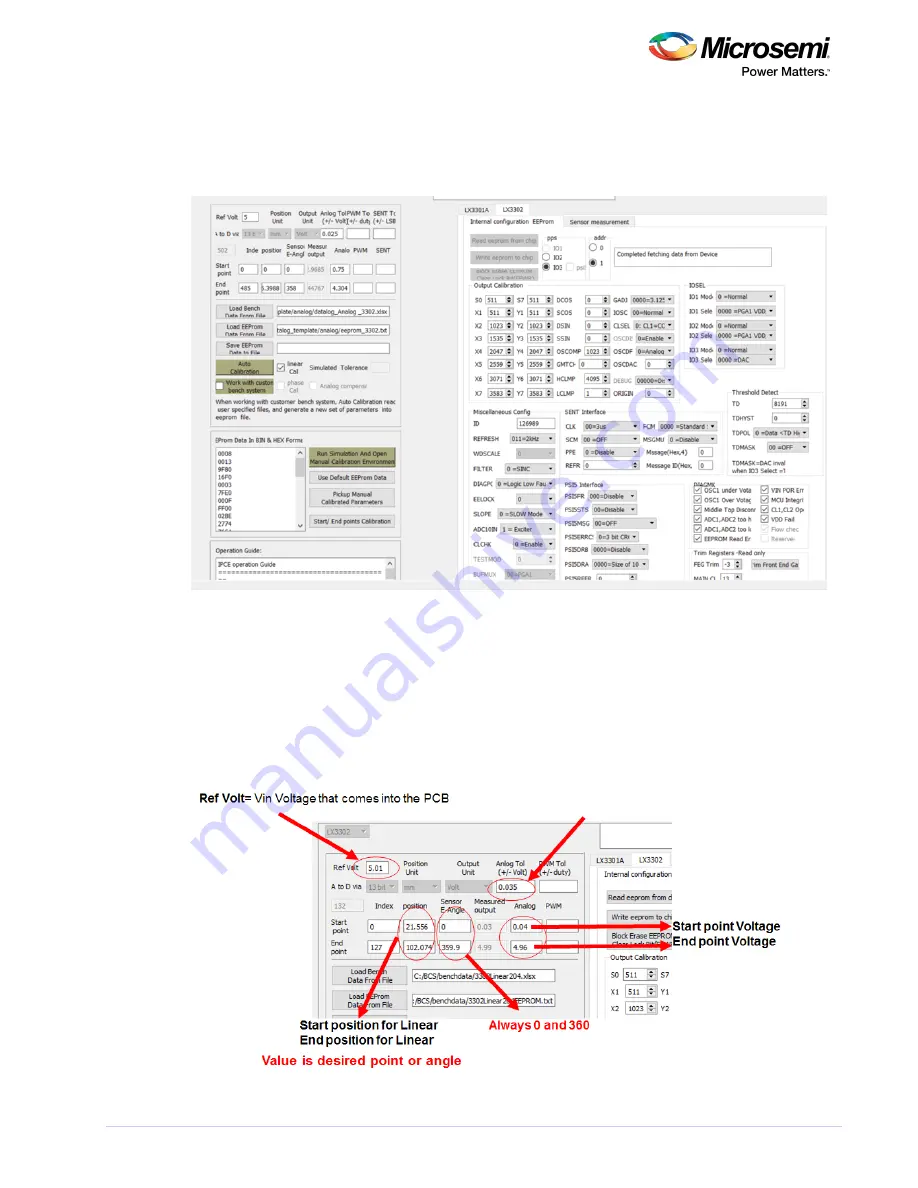
The following image shows the calibration condition settings. The example given is 35 mV. This means 
that any given position on the output could be accurate within 35 mV.

IF ANALOG (DAC) output is used, measure VIN from the sensor board connector.

Analog Tol= the Autocal system will calibrate up to this accuracy.

Figure 24 • Calibration Condition Setting

Summary of Contents for LX3301A

Page 1: ...LX3301A LX3302A Auto Calibration User Guide Preliminary May 2018...

Page 2: ...Data Capture Preparation Using LX3302A 9 3 4 Data Validation 12 4 Calibration Using IPCE 13 4 1 Loading Data EEPROM into IPCE 13 4 2 Example Data and EEPROM Parameters Loaded 14 4 3 Calibration Condit...

Page 3: ...on 1 0 1 1 Revision History The revision history describes the changes that were implemented in the document The changes are listed by revision starting with the most current publication 1 1 Revision...

Page 4: ...stall and validate the software for the LX3301A LX3302A device 1 Connect the dongle to the computer 2 Connect the sensor PCB to the dongle 3 Place your target at a desired air gap The first three step...

Page 5: ...ion Environment IPCE as shown Figure 2 Launch IPCE 6 Verify that the port has opened as shown Figure 3 Verify Port Has Opened Note If it cannot recognize the dongle then install the driver provided us...

Page 6: ...tly If the result is as shown in the following three images then communication has not been done correctly Note Place the target with proper air gap distance if it won t read EEPROM correctly Then try...

Page 7: ...is not connected or AOUT IO3 is stuck high All data is 0000 Place the target in the proper position or fix AOUT IO3 shorted GND Figure 6 Example of IC Detects Fault or AOUT IO3 Stuck at 0 V The follow...

Page 8: ...Confidential LX3301A LX3302A Auto Calibration User Guide Revision 1 0 6 8 Use the default EEPROM data and write this default EEPROM data to the chip as shown in the following image Figure 8 Write Def...

Page 9: ...nalog data Figure 10 Data Format for Analog Data SP position Start point position on the data target position See the red arrow EP position End point position on the data See the blue arrow SP AOUT V...

Page 10: ...m 0 5 V 20 mm negative slope SP_AOUT 0 5 V EP_AOUT 4 5 SP position 20 EP position 3 Figure 11 Data Format for Analog The following image shows the data format for PWM data Figure 12 Data Format for PW...

Page 11: ...How to Capture Data Using IPCE Manually If data cannot be captured by a motorized automatic system then it can be done manually using IPCE A position measurement tool is required to get an accurate p...

Page 12: ...re Configuration 2 In the tab check IO2 and IO3 to see the measurements as shown Sensor measurement Figure 16 Sensor Measurements Tab 3 Press to record the data Move the target to the next position an...

Page 13: ...Press the button if data is captured by IPCE Save Datalog Figure 17 Update Target Output After completing a run with default parameter save all the data in one of the templates shown previously or if...

Page 14: ...libration User Guide Revision 1 0 12 3 4 Data Validation After data collection check if the data is valid to use In Excel plot and check that the curve is not intermittent and does not have drops The...

Page 15: ...as shown Load Bench Data From File Figure 20 Load Bench Data From File 2 Select the data file captured and prepared as given data format Excel 3 When the following window appears click OK Figure 21 Su...

Page 16: ...23 Example Loaded Data and EEProm Para Loaded 4 3 Calibration Condition Settings The following image shows the calibration condition settings The example given is 35 mV This means that any given posit...

Page 17: ...from the file is loaded phase and calibration can be completed 1 Check the box for both and linear Cal phase Cal 2 Click Auto Calibration Figure 25 Auto Calibration Calibration is complete The result...

Page 18: ...l phase Cal 2 Press Then the new values of SSIN SCOS and GMTCH should appear Auto Calibration 3 Burn this into the IC by write Eeprom to chip Figure 27 Auto Calibration of Phase 5 Click to open the ma...

Page 19: ...le simulation Figure 29 Example Simulation 4 6 Save Calibrated Result into EEPROM The following steps describe how to save the calibrated result into EEPROM 1 When the auto calibration simulation resu...

Page 20: ...ed rate as shown Figure 33 Refresh 6 Click write eeprom to chip 7 Click Then select the proper file save location and type in the filename to Save EEProm Data to File store for example SN_01_Final_eep...

Page 21: ...ers 6 Select the Sensor measurement tab to view the measurements 5 2 Collect Measurements with Default Parameters At this moment in calibration measurement data needs to be collected using default par...

Page 22: ...0 20 The following image shows how to set the calibration condition in the datalog file Figure 35 Calibration Condition Setting The following image shows an example datafile with a negative slope Figu...

Page 23: ...tocal Figure 37 Example of Post Autocal 5 3 Save EEPROM Data to File After you have saved the default parameters file save the EEPROM data to file Save the current EEPROM parameters You can do this by...

Page 24: ...sibility to independently determine suitability of any products and to test and verify the same The information provided by Microsemi hereunder is provided as is where is and with all faults and the e...

Reviews: