


ENGLISH
cable (Fig. 1 pos ) from the battery’s positive
terminal.
3. Take away the magnet.
4. Access™ BMU is now reset to the factory set
network.
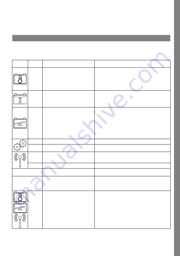
Status indicator
Status indicator on the control panel.
See
Indica-
tion
Status
Cause
Action
Flashes
The battery is too warm.
a. Allow the battery to cool.
b. Reduce the workload on the battery.
c. In Access™ Service tool: Check that the battery’s
temperature level for alarm indication corresponds
with the battery manufacturer's recommendation.
Flashes
a. Low electrolyte level.
b. The electrolyte level and battery
temperature sensor is installed
incorrectly.
a. Top up the battery water.
b. Check the installation of the electrolyte level and
battery temperature sensor, see
step 5.
Flashes
Voltage imbalance between the
battery’s cells.
a. Equalize charge the battery.
b. Check the condition of the battery cells.
c. Check that the black cable Fig. 1 pos is connected to
the battery’s negative terminal.
d. Check the set parameters for the current sensor
position and indication level through Accessthe ™
Service tool.
Flashes
Time and date set incorrectly.
Set the time and date with the Access™ Service tool.
Lit
Time and date are set correctly, unit
works.
Flashes
The battery monitoring unit is
searching for a network to connect to
or has connection permitted enabled.
Take away the magnet from the magnetic switch.
Lit
The unit is connected to a network.
All indicators
flashing
An identification request has been
sent from the Access™ Service tool.
The indicators go out automatically after the requested
identification time has elapsed, normally 10 seconds.
No indicators lit
No supply voltage.
Check the battery monitoring unit’s connections to the
battery’s positive terminal and current sensor.
Check the fuse on the cable between the battery
monitoring unit and the battery’s positive terminal.
These
are lit,
the
others
are off.
Software in Access™ BMU is being
updated.
Wait until Access™ BMU starts up, this normally takes
15-30 seconds. Do not disconnect the supply voltage.
7
Summary of Contents for Access BMU PRO UL
Page 2: ......