background image

© Microhard Systems Inc. 


178 

Appendix B:  IP-Passthrough Example (Page 1 of 2) 

By completing the Quick Start process, a user should have been able to log in and set up the 

IPn4G

 to 

work with their cellular carrier. By completing this, the modem is ready to be used to access the internet 
and provide mobile connectivity. However, a common application of the 

IPn4G

 is to access connected 

devices remotely. In order to do this, the 

IPn4G

 must be told how to deal with incoming traffic, where to 

send it to. To accomplish this there are three options : 


- IP-Passthrough 


- Port Forwarding 


- DMZ (a type of Port Forwarding) 

 
In this section we will talk about IP-Passthrough and how to configure the IPn4G and the connected 
device/PC to work with IP-Passthrough. IP-Passthrough means that the IPn4G is transparent, and all 
outside (WAN) traffic is simply sent directly to a single device connected to the physical LAN RJ-45 port on 
the IPn4G (With exception of port 80, which is retained for remote configuration (configurable). Also, any 
traffic that is sent to the RJ45 port is sent directly out the WAN port and is not processed by the IPn4G.  
 
IP-Passthrough is ideal for applications where only a single device is connected to the IPn4G, and other 
features of the IPn4G are not required. When in pass-through mode, most features of the IPn4G are 
bypassed, this includes the serial ports, the GPS features, VPN, the Firewall, and much more. The 
advantage of IP-Passthrough is that the configuration is very simple. 
 
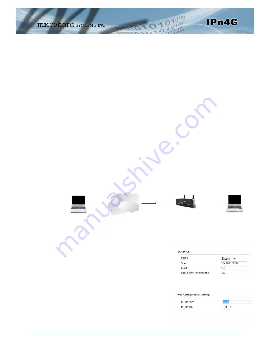
In the example below we have a IPn4G connected to a PC (PC2). The application requires that PC1 be 
able to access several services on PC2. Using Port Forwarding this would require a new rule created for 
each port, and some applications or services may require several ports so this would require several rules, 
and the rules may be different for each installation, making future maintenance difficult. For IP-
Passthrough, PC1 only needs to know the Public Static IP Address of the IPn4G, the IPn4G would then 
automatically assign, via DHCP, the WAN IP to the attached PC2, creating a transparent connection. 


Step 1 
 

Log into the IPn4G (Refer to Quick Start), and ensure that DHCP is 
enabled on the 

Network >  LAN

 page. 


Step 2  
 

Since PC2 requires port 80 to be used as its Web server port, port 
80 cannot be used on the IPn4G, by default it retains this port for 
remote configuration. To change the port used by the IPn4G, 
navigate to the 

System > Settings

 page as seen below. For this 

example we are going to change it to port 8080. When changing 
port numbers on the IPn4G, it is recommended to reboot the unit 
before continuing, remember the new WebUI port is now 8080 when 
you log back into the IPn4G. (e.g. 192.168.168.1:8080). 

Cellular Network/ 

Internet 

WAN IP: 74.198.186.193 
(Cellular Carrier) 
 
LAN IP: 74.198.186.1 (Used 
for WebUI from LAN) 

PC2:  (DHCP) 
WebServer running on port 80 

Connected to RJ45 
LAN Ethernet Port.


Wireless Cellular 

Connection


PC1: Connected to 

internet.


Summary of Contents for IPN4G

Page 1: ...t Bridge Serial Gateway Document IPn4G Operating Manual v1 4 pdf FW v1 1 0 Build1084 16 Operating Manual May 2015 150 Country Hills Landing NW Calgary Alberta Canada T3K 5P3 Phone 403 248 0028 Fax 403 248 2762 www microhardcorp com ...

Page 2: ...TED NO FUNCTIONAL WARRANTY Indemnification The Purchaser shall indemnify Microhard Systems Inc and its respective directors officers employees suc cessors and assigns including any subsidiaries related corporations or affiliates shall be released and dis charged from any and all manner of action causes of action liability losses damages suits dues sums of money expenses including legal fees genera...

Page 3: ...y illustrations that further elaborate on the accompanying text but also several symbols which you should be attentive to Caution or Warning Usually advises against some action which could result in undesired or detrimental consequences Point to Remember Highlights a key feature point or step which is noteworthy Keeping these in mind will simplify or enhance device usage Tip An idea or suggestion ...

Page 4: ...ance operations at closer than this distance is not recommended The antenna being used for this transmitter must not be co located in conjunction with any other antenna or transmitter This device can only be used with Antennas approved for this device Please contact Microhard Systems Inc if you need more information or would like to order an antenna WARNING WARNING MAXIMUM EIRP FCC Regulations all...

Page 5: ... code will ensure a safe and compliant installation Do not connect or disconnect equipment unless power has been switched off or the area is known to be non hazardous Installation operation and maintenance of the transceiver should be in accordance with the transceiver s installation manual and the National Electrical Code Tampering or replacement with non factory components may adversely affect t...

Page 6: ...rder Load Recorder Updated Fire wall Updated VPN Gateway Type etc Added Modbus Updated misc screen shots misc formatting Etc Based on Firmware v1 1 0 r1028 bin PEH Mar 2013 1 2 Misc formatting updates Updated WiFi antenna to RP SMA Female PEH Mar 2013 1 21 Corrected LTE Band Spec PEH Apr 2013 1 22 Added PoE information PEH Apr 2013 1 23 Added Corrected Digital I O pins location PEH Apr 2013 1 24 C...

Page 7: ... Rear 23 4 0 Configuration 24 4 0 Web User Interface 24 4 0 1 Logon Window 25 4 1 System 26 4 1 1 Summary 26 4 1 2 Settings 27 Host Name 27 Syslog Settings 28 Date Time 29 NTP Server Settings 29 HTTP HTTPS Port Settings 30 4 1 3 Access Control Users Passwords 31 4 1 4 Services 33 4 1 5 Maintenance 35 Version Information 35 Firmware Upgrade 35 Reset to Default 36 Backup Restore Configurations 36 4 ...

Page 8: ... Interface 74 Operating Mode 75 TX Rate 75 TX Power 76 SSID 76 AP Isolation 76 Encryption Type 77 4 4 3 Hotspot 78 4 5 Comport 81 4 5 1 Status 81 4 5 2 COM0 1 Settings 82 Data Baud Rate 83 IP Protocol Config 86 TCP Client 86 TCP Server 86 TCP Client Server 87 UDP Point to Point 87 UDP Point to Multipoint P 87 UDP Point to Multipoint MP 88 UDP Multipoint to Multipoint 88 SMTP Client 89 PPP 90 GPS T...

Page 9: ... 10 4 1 Configuration 130 4 10 4 2 Message Structure 131 4 10 4 3 Message Payload 132 4 10 5 Modbus 133 4 10 5 1 TCP Modbus 133 4 10 5 2 Serial COM Modbus 135 4 10 5 3 Modbus Data Map 136 4 10 6 Websocket 137 4 10 7 Site Survey 139 4 10 8 Ping 140 4 10 9 TraceRoute 141 5 0 AT Command Line Interface 142 5 1 AT Command Overview 142 5 1 1 Serial Port 142 5 1 2 Telnet 143 5 2 AT Command Syntax 144 5 3...

Page 10: ...2 or RS485 interface the IPn4G can be used in a limitless number and types of applications such as 1 1 Performance Features Key performance features of the IPn4G include High speed backbone IP video surveillance Voice over IP VoIP Ethernet wireless extension WiFi Hotspot Legacy network device migration SCADA PLC s Modbus Hart Facilitating internetwork wireless communications Fast 4G LTE Link to Wi...

Page 11: ...ease see the specification sheets available on the Microhard web site http www microhardcorp com for your specific model Electrical General Cellular Supported Bands Data Features SIM Card 1 8 3 0 V WiFi Frequency 2 4 GHz Spread Method CCK QPSK BPSK OFDM BPSK QPSK QAM16 QAM32 QAM64 Data Rates 802 11b g TX Power Adjustable Up to 30dBm Data Encryption WEP WPA PSK WPA2 PSK WPA WPA2 PSK Subject to Expo...

Page 12: ...igital I O 1 Inputs 1 Outputs Environmental Operation Temperature 40o F 40o C to 185o F 85o C Humidity 5 to 95 non condensing Mechanical Dimensions 2 25 57mm X 3 85 98mm X 1 5 45mm Weight Approx 250 grams Connectors Antenna Wi Fi RP SMA Female Cellular 2x SMA Female Main DIV GPS Uses Diversity Antenna Data RS232 COM1 DB 9 Female Digital I O RS232 Data DB 9 Female RS485 SMT 6 Pin Micro MATE N LOK A...

Page 13: ... valid SIM Card for your Wireless Carrier must be installed Insert the SIM Card into the slot as shown below 2 2 Getting Started with Cellular Connect the Antenna s to the applicable ANTENNA jack s of the IPn4G Connect the power connector to the power adapter and apply power to the unit the RF SGNL LED s will flash during boot up once they stop proceed to the next step SIM Card Slot To reset to fa...

Page 14: ... and enter the IP address 192 168 168 1 into the ad dress bar The IPn4G will then ask for a Username and Password Enter the factory defaults listed below 192 168 168 1 The factory default network settings IP 192 168 168 1 Subnet 255 255 255 0 Gateway 192 168 168 1 The Factory default login User name admin Password admin The factory default login User name admin Subnet admin It is always a good ide...

Page 15: ...change the APN click on the Carrier Settings tab and enter the APN sup plied by your carrier in the APN field Some carriers may also require a User name and Password Once the APN and any other required information is entered to connect to your carrier click on Submit Return to the System Summary tab 2 0 Quick Start Auto APN Introduced in firmware version v1 1 0 r1038 the IPn4G will attempt to dete...

Page 16: ...you may need to add the DNS Servers shown in the Carrier Status Menu to you PC to enable internet access Congratulations Your IPn4G is successfully connected to your Cellular Carrier The next section gives a overview on enabling and setting up the WiFi Wireless features of the modem giving 802 11 devices network access To access devices connected to IPn4G remotely one or more of the following must...

Page 17: ...p WiFi Use Section 2 2 Getting Started with Cellular to connect power up and log in and configure the Carrier in a IPn4G Click on the Wireless Radio1 Tab to setup the WiFi portion of the IPn4G Cell Tower 2 0 Quick Start 4G LTE 802 11b g In Radio1 Phy Configuration ensure the mode is set for 802 11BG In the Radio1 Virtual Interface en sure that the Mode is set for Access Point Enter a name for the ...

Page 18: ...een set up See Section 2 3 WiFi devices should be able to de tect and connect to the IPn4G On a WiFi enabled PC Device the SSID of MyNetwork that was created in the last example should be visible Connect to that SSID and enter the password Once connected the status should change to connected and network access should be enabled 2 0 Quick Start ...

Page 19: ... Microhard Systems Inc 19 The status of the WiFi connection should also be visible in the Wireless Status tab in the WebUI as seen below 2 0 Quick Start ...

Page 20: ...e if you are familiar with one unit you will be familiar with all units The IPn4G features Standard Connectors for 1 Ethernet Ports RJ45 COM0 Data Port RS232 DB9 COM1 Console Port RS232 DB9 4 Pin MATE N LOK Type Connector for Power 6 Pin MATE N LOK Type Connector for RS485 Data Cellular Antenna SMA Female Antenna Connection x2 WiFi Antenna RP SMA Female Antenna Connection Optional Status Diagnosti...

Page 21: ... Top View Dimensions Drawing 3 2 IPn4G Front View Dimensions Drawing 3 3 IPn4G Rear View Dimensions Note All dimension units Millimeter 32 07 52 20 8 60 11 53 56 20 69 81 119 70 Ø7 00 R3 50 108 50 97 70 11 00 5 40 5 60 5 60 5 40 97 70 119 70 37 20 2 60 34 60 119 70 37 20 97 70 11 00 2 60 O I ...

Page 22: ...ssing the Web User Interface RF Red SGNL Green LED s When the unit is equipped with WiFi the RF SGNL LED s indicate WiFi activity In units not equipped with WiFi the RF SGNL LED s indicate carrier cellular traffic Also during system bootup the RF SGNL LED s will flash Receive Signal Strength Indicator RSSI 3x Green As the received signal strength increases starting with the furthest left the numbe...

Page 23: ...The IPn4G can also be powered using Passive PoE on the Ethernet Port via a PoE injector 3 1 2 Connectors and Indicators 3 1 2 2 Rear On the back of the IPn4G is the Data COM0 port RS485 422 interface as well as the power connections The unit also has the SMA F connectors for the Main TX RX the Diversity RX antenna s and a RP SMA Female connector for the optional WiFi antenna Name Data Port Input o...

Page 24: ...o PC NIC card using an Ethernet cable apply power to the IPn4G and wait approximately 60 seconds for the system to load open a web browser and enter the factory default IP address of the unit 192 168 168 1 logon window appears log on using default Username admin Password admin use the web browser based user interface to configure the IPn4G as required refer to Section 2 0 Quick Start for step by s...

Page 25: ... the password appears as dots as shown in the image below This display format prohibits others from viewing the password The Remember my password checkbox may be selected for purposes of convenience however it is recommended to ensure it is deselected particularly once the unit is deployed in the field for one primary reason security Image 4 0 2 Logon Window For security do not allow the web brows...

Page 26: ...ort for the WebUI Access Control Change passwords create new users Services Enable Disable RSSI LED s SSH and Telnet services Maintenance Version information firmware Upgrades reset to defaults configuration backup and restore Reboot Remotely reboot the system Logout Logout of the current browser session 4 1 1 System Summary The System Summary screen is displayed immediately after initial login sh...

Page 27: ...onvenient cross reference for the unit s WAN IP address This name appears when logged into a telnet session or when the unit is reporting into Microhard NMS System Host Name Values characters IPn4G wifi varies The Host Name must not be confused with the Network Name SSID Wireless Configuration menu The description field is a general purpose text field that can be used to provide additional informa...

Page 28: ...nerated accordingly The screenshot below shows a sample from a simple Syslog Server application System Log Server IP Name Values 0 0 0 0 Enter the UDP port number on the Syslog Server where the actual service is running Consult with the documentation of your chosen Syslog Server for the correct port number The most common port is 514 which has been set as the default System Log Server Port Values ...

Page 29: ...ver The options and menus available will change depending on the current setting of the Date and Time Setting Mode as seen below Image 4 1 3 System Settings Time Settings Network Time Protocol NTP can be used to synchronize the time and date or computer systems with a centralized referenced server This can help ensure all systems on a network have the same time and date Date and Time Setting Mode ...

Page 30: ... of web protocol used for the WebUI configuration Select between HTTP basic and HTTPS SSL secure or Both that are running on the modem Values port HTTP HTTPS BOTH HTTP HTTPS Port The default web server ports for the web based configuration tools for HTTP is TCP 80 and for HTTPS is TCP 443 If changes are required keep in mind it must be specified in a internet browser to access the unit example htt...

Page 31: ...leted as required as seen in the Users menu below Image 4 1 5 Access Control Password Change Enter a new password for the admin user It must be at least 5 characters in length The default password for admin is admin New Password Values characters admin min 5 characters Confirm Password The exact password must be entered to confirm the password change if there is a mistake all changes will be disca...

Page 32: ... 1 6 Access Control Users Enter the desired username Minimum or 5 character and maximum of 32 character Changes will not take effect until the system has been restarted Username Values characters no default Min 5 characters Max 32 characters Password Confirm Password Passwords must be a minimum of 5 characters The Password must be re entered exactly in the Confirm Password box as well no default m...

Page 33: ...cle Image 4 1 7 System Services The IPn4G has the ability to turn off the RSSI LED s The RSSI value can still be read from the unit but the status will not be visible on the unit itself RSSI LED Values selection Start Restart Stop Throughput Test Server For testing purposes the IPn4G has an internal iperf server that can be used to test unit performance The user must install a iperf client to use ...

Page 34: ...This port is reserved for internal use future use FTP Server Values selection Start Restart Stop Microhard Sh Custom SSH Port Reserved for internal use Start Restart Stop Values selection Telnet Service Using the Telnet Service Enable Disable function you can disable the Telnet service Port 23 from running on the IPn4G Start Restart Stop Values characters ...

Page 35: ... during the upgrade process This will upgrade and return the unit to factory defaults including the default IP Addresses and passwords Not checking the box will retain all settings during a firmware upgrade procedure Erase Current Configuration Values check box unchecked Firmware Image Use the Browse button to find the firmware file supplied by Microhard Systems Select Upgrade Firmware to start th...

Page 36: ...e Browse button to find the backup file that needs to be restored to the unit Use the Check Restore File button to verify that the file is valid and then the option to restore the configuration is displayed as seen above The option is available to keep the current carrier settings rather than replace them with the settings contained in the Config file Backup Restore Configuration The configuration...

Page 37: ... Microhard Systems Inc 37 4 0 Configuration 4 1 6 System Logout The logout function allows a user to end the current configuration session and prompt for a login screen Image 4 1 10 System logout ...

Page 38: ...ation 4 1 7 System Reboot The IPn4G can be remotely rebooted using the System Reboot menu As seen below a button OK reboot now is provided Once pressed the unit immediately reboots and starts its boot up procedure Image 4 1 11 System Reboot ...

Page 39: ...rk 4 2 1 Network Status The Network Status display gives a overview of the currently configured network interfaces including the Connection Type Static DHCP IP Address Net Mask Default Gateway DNS and IPv4 Routing Table Image 4 2 1 Network Network Status ...

Page 40: ...ddresses from a DHCP server Advantage Ensures unique IP addresses are assigned from a central point DHCP server within a network Disadvantage The address of a particular device is not known and is also subject to change STATIC addresses must be tracked to avoid duplicate use yet they may be permanently assigned to a device Image 4 2 3 Network Add Edit LAN Interface LAN Add Edit Interface The IPn4G...

Page 41: ...IP Address no default A simple way of looking at what the gateway value should be is If a device has a packet of data is does not know where to send send it to the gateway If necessary and applicable the gateway can forward the packet onwards to another network A GATEWAY is a point within a network that acts as an entrance to another network In typical networks a router acts as a gateway DNS Domai...

Page 42: ...ed as clients and other wireless devices such as 802 11 connections DHCP Values selection On Off Select the starting address DHCP assignable IP Addresses The first octets of the subnet will be pre set based on the LAN IP configuration and can not be changed Start Values IP Address 192 168 168 100 Image 4 2 4 Network Add Edit Interface DHCP Set the maximum number of IP addresses that can be assigne...

Page 43: ...er Values IP Address IP Address Enter the Domain Name for the DHCP devices Domain Name Values string IP Address Enter the address of the WINS NBNS NetBIOS Server The WINS server will translate computers names into their IP addresses similar to how a DNS server translates domain names to IP addresses WINS NBNS Servers Values IP Domain no default Select the method used to resolve computer names to I...

Page 44: ...dress in the next field Must use the format AB CD DF 12 34 D3 It is not case sensitive but the colons must be present MAC Address Values MAC Address no default Enter the IP Address to be assign to the device specified by the MAC address above IP Address Values IP Address minutes Static Addresses This section displays the IP address and MAC address currently assigned through the DCHP service that a...

Page 45: ...P server must be defined if it is required to provide DHCP services to connecting devices In most cases the WIFI interface would be setup to allow the IPn4G to operate as a Client to another Access Point AP Using this menu it can be decided to use DHCP to obtain an IP address and related networking information from the connected Access Point or it could be setup with a static IP address that is pa...

Page 46: ... the IPn4G where to send data Image 4 2 6 Network Routes Routes can be names for easy reference or to describe the route being added Name Values characters no default Enter the network IP address for the destination Destination Values IP Address 192 168 168 0 Specify the Gateway used to reach the network specified above Gateway Values IP Address 192 168 168 1 Enter the Netmask for the destination ...

Page 47: ...give certain routes priority the lower the metric is the better the route The more hops it takes to get to a destination the higher the metric Metric Values Integer 0 Define the exit interface Is the destination a device on the LAN or the WAN for the IPn4G would be the cellular connection Interface Values Selection LAN WAN 4G WIFI None ...

Page 48: ... network layer protocols not supported by traditional VPN This allows IP packets to travel from one side of a GRE tunnel to the other without being parsed or treated like IP packets Each GRE tunnel must have a unique name Up to 10 GRE tunnels are supported by the IPn4G Name Values Chars 32 gre Image 4 2 8 Network Edit Add GRE Tunnel Refer to Appendix G GRE Example for a working example of how to s...

Page 49: ...traveling through the GRE tunnel Values value 1 255 Gateway IP Address This is the WAN IP Address of the IPn4G this field should be populated with the current WAN IP address Values IP Address varies Tunnel IP Address This is the IP Address of the local tunnel Values IP Address varies Key Enter a key is required key must be the same for each end of the GRE tunnel Values chars none Netmask Enter the...

Page 50: ... Subnet Mask The subnet mask for the local network subnet Values IP Address varies Subnet IP Address Enter the subnet address for the local network Values IP Address varies Remote Setup The remote setup tells the IPn4G about the remote end the IP address to create the tunnel to and the subnet that is accessible on the remote side of the tunnel Subnet Mask The is the subnet mask for the remote netw...

Page 51: ...nd processing of the information sent by a device either responses to queries or device sourced traps The MIB in the device relates subroutine addresses to objects in order to read data from or write data to variables in the device An SNMPv1 agent accepts commands to retrieve an object retrieve the next object set and object to a specified value send a value in response to a received command and s...

Page 52: ...ate SNMP queries Being part of the community allows the SNMP agent to process SNMPv1 and SNMPv2c requests This community name has only READ priority Read Only Community Name Values string public Also a plain text password mechanism used to weakly authenticate SNMP queries Being part of the community allows the SNMP agent to process SNMPv1 and SNMPv2c requests This community name has only READ WRIT...

Page 53: ...et to AuthNoPriv or AuthPriv Not supported V3 User Authentication Password Values string 00000000 SNMPv3 user s encryption password Only valid when V3 User Authentication Level set to AuthPriv see above Authpriv is currently not supported on the IPn4G b V3 User Privacy Password Values string 00000000 Select which version of trap will be sent should a failure or alarm condition occur SNMP Trap Vers...

Page 54: ...icrohard Radio employ a discovery service that can be used to detect other Microhard Radio s on a network This can be done using a stand alone utility from Microhard System s called IP Discovery or from the Tools Discovery menu The discovery service will report the MAC Address IP Address Description Product Name Firmware Version Operating Mode and the SSID Specify the port running the discovery se...

Page 55: ...IP If auto detect is selected the IPn4G will detect and monitor DHCP assigned IP address Status Enable or disable the local device monitoring service Disable Enable Values selection Fixed local IP Auto Detected IP Values selection Local IP Setting This field is only shown if Fixed Local IP is selected for the IP Mode Enter the static IP to be monitored in this field 0 0 0 0 Values IP Status Timeou...

Page 56: ...ect between Auto where the IPn4G will decide the best port settings based on a negotiation with the connected device It can also be set to manual where the Speed and Duplex can be set manually Auto Manual Values selection 100Mbit s 10Mbit s Values selection Duplex If the mode above is set to manual it is possible to select the duplex mode of the Ethernet port Choose between Full and Half duplex Fu...

Page 57: ...riety of information can be found here such as Activity Status Network Name of Wireless Carrier connected Data Service Type WCDMA HSPA HSPA LTE etc Frequency band Phone Number etc Not all statistics parameters displayed are applicable The Received and Transmitted bytes and packets indicate the respective amount of data which has been moved through the radio The Error counts reflect those having oc...

Page 58: ...The parameters within the Carrier Configuration menu must be input properly they are the most basic requirement required by your cellular provider for network connectivity Carrier Status is used to Enable or Disable the connection to the Cellular Carrier By default this option is enabled Carrier Status Values Selection Enable Disable This option is used to prevent the modem from roaming This is im...

Page 59: ...s mentioned above it is recommended to use the Auto mode for IP Passthrough IP Passthrough Gateway Values no default This field is used to specify the Netmask to be used for IP Passthrough if set to manual mode As mentioned above it is recommended to use the Auto mode for IP Passthrough IP Passthrough Netmask Values no default This is a read only field that displays the current IP address assigned...

Page 60: ...merica Data Call Parameters Values string none The SIM Pin is required for some international carriers If supplied and required by the cellular carrier enter the SIM Pin here SIM Pin Values characters none The APN is required by every Carrier in order to connect to their networks The APN defines the type of network the IPn4G is connected to and the service type Most Carriers have more than one APN...

Page 61: ...ssword for the user name above May not be required by some carriers or APN s Password Values characters Carrier peer dependant In some cases the Static IP address must be entered in this field if assigned by a wireless carrier In most cases the IP will be read from the SIM card and this field should be left at the default value IP Address Values IP Address none Enter the Secondary NetBIOS Name Ser...

Page 62: ...e Status Values Selection Enable Disable Select the type of keep alive used ICMP uses a ping to reach a select destination Type Values Selection ICMP HTTP Specify a IP Address or Domain that is used to test the IPn4G connection Use the Test button to ensure that a reachable host is used Host Name Values IP or Domain 8 8 8 8 The Interval value determines the frequency or how often the IPn4G will se...

Page 63: ...s elapsed the unit will reset and attempt to re establish communication with the cellular carrier Enable or Disable the Traffic Watchdog Traffic Watchdog Values Selection Enable Disable The Check Interval tells the IPn4G how often in seconds to check for wireless traffic to the cellular carrier 1 60000 seconds Check Interval Values seconds 1 The Reboot Timer will reset the unit if there has been n...

Page 64: ...Selection Enable Disable This is a list of supported Dynamic DNS service providers Free and premium services are offered contact the specific providers for more information customized_ddns can be selected to configure your own DDNS service if required Service Values selection changeip dyndns eurodyndns hn noip Enter a valid user name for the DDNS service selected above User Name Values characters ...

Page 65: ...ept and execute commands originating from the phone numbers in the Phone Filter List Up to 6 numbers can be added Set Phone Filter Values Selection Enable Disable MSC REBOOT Reboot system MSC NMS Send NMS UDP Report MSC WEB Send web client inquiry MSC MIOP1 open I O ouput1 MSC MIOP2 open I O ouput2 MSC MIOP3 open I O ouput3 MSC MIOP4 open I O ouput4 MSC MIOC1 close I O ouput1 MSC MIOC2 close I O o...

Page 66: ...s Selection Enable Disable SMS Alerts can be sent to up to 6 different phone numbers that are listed here Received Phone Numbers Values Selection no default SMS alerts when active will be sent out at the frequency defined here Time Interval s Values Seconds 300 A text field that allows up to 30 characters to add an alias or other information that will be included with the SMS message Device Alias ...

Page 67: ...no link SMS Alerts can be sent based on the state changes of the Digital I O lines I O Status Values Selection Disable IO Check Enable INPUT Changed Enable Output Changed Enable INPUT or OUTPUT Changed Set the low threshold for RSSI alerts When the RSSI drops below this value an alert will be sent indicating poor service Low Threshold dBm Values dBm 99 Enable or disable SMS Alerts for Roaming Stat...

Page 68: ... 4 3 7 Carrier SMS SMS Command History The SMS menu allows a user to view the SMS Command History and view the SMS messages on the SIM Card Image 4 3 9 SMS SMS Send Send SMS Message The SMS messages can be sent directly from the IPn4G WebUI interface Also the SMS message history can be viewed ...

Page 69: ...setting daily and or monthly limits Notifications can be sent using SMS or Email allowing a early warning if configurable limits are about to be exceeded The usage data reported by the Data Usage Monitor may not match the data reported by the carrier but it gives the users an idea of the bandwidth consumed by the IPn4G Status Values selection If enabled the IPn4G will track the amount of cellular ...

Page 70: ... 1 31 For Monthly tracking select the day the billing data cycles begins On this day each month the IPn4G will reset the data usage monitor numbers 1 Day of Month Phone Number Values phone If SMS is selected as the notification method enter the phone number to send any SMS messages generated when the data usage exceeds the configured limits 1403 Monthly Daily Over Limit Values selection Select the...

Page 71: ... the account used to send the Email notifications Domain or IP address with the associated port as shown smtp gmail com 465 Username Values username If Email is selected as the notification method enter the username of the Email account used to send Emails gmail com Password Values string If Email is selected as the notification method enter the password of the Email account used to send Emails Mo...

Page 72: ...Mode Access Point Client MESH etc the SSID being used frequency channel information and the type of security used Traffic Status shows statistics about the transmitted and received data The IPn4G shows information about all Wireless connections in the Connection Status section The Wireless MAC address Noise Floor Signal to Noise ratio SNR Signal Strength RSSI The transmit and receive Client Connec...

Page 73: ...which wireless standard to use for the wireless network The IPn4G supports 802 11b g modes as seen here Select the appropriate operating mode from the list Mode Values selection 802 11B ONLY 802 11BG The Channel Freq setting allows configuration of which channel to operate on auto can be chosen where the unit will automatically pick a channel to operate If a link cannot be established it will try ...

Page 74: ...sions caused by obstructions RTS Thr 256 2346 Values selection On OFF The Fragmentation Threshold allows the system to change the maximum RF packet size Increasing the RF packet size reduces the need to break packets into smaller fragments Increasing the fragmentation threshold slightly may improve performance if a high packet error rate is experienced Fragment Thr 256 2346 Values selection On OFF...

Page 75: ... Access Point to extend the range and provide a wireless data connection to many clients such as stations Mesh Point Units can be configured as a Mesh Node When multiple units are configured as a Mesh node they automatically establish a network between each other SSID for each radio in a Mesh network must be the same This setting determines the rate at which the data is to be wirelessly transferre...

Page 76: ...ue for the Network Name to something unique for your network Do this for an added measure of security and to differentiate your network from others which may be operating nearby In Mesh Networks this must be the same for all IPn4G or VIP Series units participating similar to the SSID for other wireless networks MESH ID Values string no default This setting establishes the transmit power level whic...

Page 77: ...e overhead to the data thereby negatively effecting throughput to some degree The image below shows the associated configuration options Image 4 4 4 Encryption Type WEP Key Generation 4 complex WEP keys may be generated based on the supplied Passphrase Procedure Input a Key Phrase select the type of Key to be generated using the Generate Key soft button Using the same Passphrase on all IPn4G VIP S...

Page 78: ...entication service Hotspot Status Values selection Enable Disable This is the RADIUS name of your Hotspot as given by your Hotspot Service Provider Radius NAS ID Values Microhard_1 This field is used to specify which configured network is bonded to the hotspot Sub networks can be created in the Network LAN menu which are dedicated to the hotspot devices The DHCP service for the network used should...

Page 79: ...rvice Provider the name or IP address of the primary RADIUS Server Radius Server 1 Values radius hotspotsystem com As assigned by the Hotspot Service Provider the name or IP address of the alternate RADIUS Server Radius Server 2 Values radius2 hotspotsystem com The Radius Authentication Port Number The default is 1812 This is provided by your Hotspot service provider Radius Auth Port Values 1812 T...

Page 80: ...n This is a secret password between the Redirect URL and the Hotspot given by the hotspot provider UAM Secret Values hotsys123 Also called a shared key this is the RADIUS password assigned by you Hotspot provider Radius Secret Values hotsys123 ...

Page 81: ...n Image 4 5 1 Comport Status 4 5 Comport 4 5 1 Comport Status The Status window gives a summary of the serial ports on the IPn4G The Status window shows if the com port has been enabled how it is configured Connect As and the connection status ...

Page 82: ...is menu option is used to configure the serial device server for the serial communications port Serial device data may be brought into the IP network through TCP UDP or multicast it may also exit the IPn4G network on another VIP Series serial port The fully featured RS232 interface supports hardware handshaking ...

Page 83: ...l communications greater than 115200bps 921600 460800 230400 115200 57600 38400 28800 19200 14400 9600 7200 4800 3600 2400 1200 600 300 This setting determines the format of the data on the serial port The default is 8 data bits No parity and 1 Stop bit Data Format Values selection 8N1 8N2 8E1 8O1 7N1 7N2 7E1 7O1 7E2 7O2 Flow control may be used to enhance the reliability of serial data communicat...

Page 84: ...er than 1 5 characters but less than the Character Timeout value Character Timeout Values characters 0 The serial server also uses this parameter to determine the time gap inserted between frames It is measured in characters and related to baud rate Example If the baud rate is 9600bps it takes approximately 1ms to move one character With the Character Timeout set to 4 the timeout period is 4ms Whe...

Page 85: ...Data Values selection Disable Enable This option will enable or disable the MODBUS decoding and encoding features MODBUS TCP Status Values selection Disable Enable The field allows the MODBUS TCP Protection Status flag to be enabled or disabled If enabled the MODBUS data will be encrypted with the MODBUS Protection Key MODBUS TCP Protection Values selection Disable Enable MODBUS encryption key use...

Page 86: ... data is communicated from the Client to the Server Default 20001 Outgoing Connection Timeout This parameter determines when the IPn4G will terminate the TCP connection if the connection is in an idle state i e no data traffic on the serial port Default 60 seconds TCP Server In this mode the IPn4G Series will not INITIATE a session rather it will wait for a Client to request a session of it it s b...

Page 87: ...t uses to send multicast UDP packets upon receiving data from the serial port The default value is a good example of a valid multicast address Default 224 1 1 1 Multicast Port A UDP port that this IP Series will send UDP packets to The Multipoint MP see the UDP Point to Multipoint MP description stations should be configured to listen to this point in order to receive multicast packets from this I...

Page 88: ...figuration described on the previous page Default 224 1 1 1 Multicast Port The UDP port that this unit will use along with the Multicast IP Address detailed above to receive the multicast UDP packets sent by the UDP Point to Multipoint P unit Default 20001 UDP Multipoint to Multipoint Multicast IP Address A valid multicast address the unit will use to send multicast UDP packets upon receiving them...

Page 89: ... IP Name IP address or Name of SMTP Mail Server Default 0 0 0 0 Mail Recipient A valid e mail address for the intended addressee entered in the proper format Default host Message Max Size Maximum size for the e mail message Default 1024 Timeout s How long the unit will wait to gather data from the serial port before sending an e mail message data will be sent immediately upon reaching Message Max ...

Page 90: ...xpected string is received Generally this does not need to be changed Default CLIENTSERVER PPP LCP Echo Failure Number The PPP server will presume the peer to be dead if the LCP echo requests are sent without receiving a valid LCP echo reply If this happens PPP server will terminate the connection Use of this option requires a non zero value for the LCP Echo Interval parameter This option can be u...

Page 91: ... 0 Configuration IP Protocol Config Continued GPS Transparent Mode When in GPS Transparent Mode GPS data is reported out the serial port at 1 second intervals Sample output is shown below Image 4 5 3 Comport GPS Transparent Mode ...

Page 92: ...al I O pins are available on the back connector shared with the input power Input Status The WebUI will display the current state the input The I O pins are all normally open so an open status indicates that there is nothing connected to the input pin or that an event has not occurred to trigger the input The inputs have a small wetting current Vin used to detect a contact closure and prevent fals...

Page 93: ...put menu is used to open or close the output pin allowing a user to remotely trigger an The output pin on the IPn4G can be used to provide output signals which can be used to drive an external relay to control an external device Maximum recommended load for the Output Pin is 150mA 32 VDC Vin ...

Page 94: ... Location Location Map The location map shows the location on the IPn4G The unit will attempt to get the GPS coordinates from the built in GPS receiver and if unsuccessful will use the Cell ID location reported by the Cellular Carrier Image 4 7 1 GPS Location Map ...

Page 95: ...GPS Status Enable or disable the GPS polling function of the IPn4G Values Disable Enable GPS Source The IPn4G contains an embedded GPS feature in the cellular module To use the GPS features of the IPn4G a cellular antenna must be connected to the Diversity Antenna Port Values Embedded Carrier GPS TCP Port Specify the TCP port on the IPn4G where the GPS service is running and remote systems can con...

Page 96: ...r Email Reporting Image 4 7 3 GPS GPS Report Report Define Enable UDP and or Email or disable GPS Reporting Up to 4 reports can be set up and configured independently Values selection Disable UDP Report Email Report Time Interval The interval timer specifies the frequency at which the GPS data is reported in seconds Values seconds 600 ...

Page 97: ...before an update is sent Values selection Only Timer Timer AND Distance Timer OR Distance Distance Set The distance parameter allows the GPS data to only be sent when a specified distance has been traveled since the last report Values meters 1000 UDP Remote IP Port This is the IP Address and port of the remote host in which the UDP packets are to be sent Values Address Port 0 0 0 0 20175 Mail Subj...

Page 98: ...The IPn4G and GpsGate software will communicate via TCP IP however if a connection is not available it will attempt to use SMS messaging Values selection Disable Enable Tracker Mode Enable TCP Send Mode Server Command Channel By default IPn4G and GpsGate will use TCP and SMS to ensure communication between each other It is also possible to specify TCP or SMS communication only Initial setup in Tra...

Page 99: ...tion Disable Enable Motion Trigger When GPS Invalid Sending Data Specify what happens when the GPS data is invalid either use the last valid position or do not use the last valid position Values selection Not Use Last Valid Position Use Last Valid Position GpsGate TCP Mode Send IO Status When enabled the IPn4G will send the current status of the Digital I O inputs and or outputs to the GpsGate Ser...

Page 100: ...he server running the GpsGate application Values Port 30175 Server Interval Define the interval at which the IPn4G will send data to the GpsGate Server Values seconds 60 Motion Distance Set the motion threshold in which the IPn4G will be triggered to send location data Values meters 100 When GPS Invalid Sending Data Specify what happens when the GPS data is invalid either use the last valid positi...

Page 101: ...arameter to enable the GPS recording functionality of the IPn4G Values selection Disable Enable GPS Recorder Position Items Specify the maximum number of events to be recorded by the IPn4G Currently this is a fixed value at 2000 entries Values selection Max 2000 Items Record Interval Define the interval at which the IPn4G will record GPS data If there is no valid data available at the specified ti...

Page 102: ...records listed above that are to be sent to the server Values selection no default Send Mode Protocol Specify the data format protocol type for the data to be sent Values selection NMEA via UDP NMEA via TCP GpsGate via UDP GpsGate via TCP Plain Text via UDP Plain Text via TCP Server Address IP Port Enter the address or IP address and port number of the remote server to which the data is to be sent...

Page 103: ...ge 4 8 1 Firewall Status 4 8 Firewall 4 8 1 Firewall Status Firewall Status allows a user to see detailed information about how the firewall is operating The All Filter Nat Raw and Mangle options can be used to view different aspects of the firewall ...

Page 104: ...s Access to ports 80 HTTP and 443 HTTPS if enabled is still available unless disabled in the WAN Remote Management option Values Block Allow LAN to WAN Access Control Allows or Blocks traffic from the LAN accessing the WAN unless specified otherwise using the Access Rules MAC and IP List configuration Values Block Allow For best practices and to control data usage it is critical that the firewall ...

Page 105: ... is used to define how the rule handles the connection request ACCEPT will allow a connection while REJECT error and DROP quietly dropped will refuse connections This is configured based on how the WAN 4G Request and LAN to WAN 4G Access Control are configured in the previous menus Values selection ACCEPT DROP REJECT Source Select the zone which is to be the source of the data traffic WAN applies ...

Page 106: ...e LAN refers to local connections on the IPn4G Ethernet WiFi Values selection LAN WAN Additional LAN Interfaces None Destination IPs Match incoming traffic from the specified destination IP range Boxes accept single IP Addresses without network masks example 192 168 1 0 to 192 168 1 255 represents all IP Addresses in the 192 168 1 0 24 network Put same IP in both boxes for a single IP match Values...

Page 107: ...d in combination with other firewall features but the Firewall must be enabled for Port forwarding to be in effect If the WAN Request is blocked on the General Tab additional rules and or IP Lists must be set up to allow the port forwarding traffic to pass through the firewall IP Passthrough Carrier Settings is another option for passing traffic through the IPn4G in this case all traffic is passed...

Page 108: ...N IP entered above Values Port 3000 Exception TCP Port Enter a exception port number that will NOT be forwarded to the DMZ server IP Usually a configuration or remote management port HTTP Port 80 or HTTPS Port 443 by default that is excluded to retain external control of the IPn4G Values Port 0 DMZ Server IP Enter the IP address of the DMZ server on the LAN side of the IPn4G Values IP Address 192 ...

Page 109: ...allowing connections based on the IP Address Subnet MAC IP List can be used alone or in combination with LAN to WAN 4G Access Control to provide secure access to the physical ports of the IPn4G Firewall MAC List Configuration Rule Name The Rule Name field is required to give the rule a convenient name for reference Each rule must have a unique name up to 10 characters in length Values 10 chars MAC...

Page 110: ...t Source IP Address Specify the specific IP or range A range of 0 0 0 0 to 255 255 255 255 will allow block all source IP s Values IP Address 192 168 0 0 Action The Action is used to define how the rule handles the connection request ACCEPT will allow a connection while REJECT error and DROP quietly dropped will refuse connections Values selection ACCEPT DROP REJECT Destination Address Optional en...

Page 111: ...mage 4 8 6 Firewall Reset 4 8 6 Firewall Reset The Reset menu allows a user to reset the Firewall on the IPn4G returning the settings to those found in a factory default state This only resets the Firewall and not any other configuration parameters ...

Page 112: ...a tunnel between the IPn4G and a remote network The IPn4G supports VPN IPsec Gateway to Gateway site to site tunneling meaning you are using the IPn4G to create a tunnel to a network with VPN capabilities Another IPn4G or VPN capable device The IPn4G can also operate as a L2TP Server allowing users to VPN into the unit from a remote PC and a L2TP Client ...

Page 113: ...e a tunnel between two VPN devices such as an IPn4G and another device another IPn4G or Cisco VPN Router or another vendor The local and remote group settings will need to be configured below to mirror those set on the other VPN device Tunnel Name Enter a name for the VPN Tunnel Up to 16 different tunnels can be created each requiring a unique name Values chars tunnel1 ...

Page 114: ...of the remote VPN router choose IP Address and then enter the address IP Server ID Choose this option if this router has a static WAN IP address and a server id The WAN IP address appears automatically For the Remote Security Gateway Type an extra field appears If you know the IP address of the remote VPN router choose IP Address and then enter the address Dynamic IP Server ID Choose this option i...

Page 115: ...connection See Local Group Setup for details Values selection IP Only IP Server ID Dynamic IP Server ID Server ID This option appears when the Remote Security Gateway Type specifies that the Server ID is required for the connection The Server ID must be in the format name where name can be anything Both routers must know each others names to establish a connection Values IP Address no default Next...

Page 116: ...entication used by the remote VPN router Values selection md5 sha1 Phase 1 Encryption Select value to match the Phase 1 Encryption type used by the remote VPN router Values selection 3des aes aes128 aes256 IPsec Setup Phase 1 DH Group Select value to match the values required by the remote VPN router Values selection modp1024 modp1536 modp2048 Subnet IP Address Define the remote network by specify...

Page 117: ...password DPD Delay s Dead Peer Detection is used to detect if there is a dead peer Set the DPD Delay seconds as required Values seconds 32 DPD Timeout s Set the DPD Dead Peer Detection Timeout seconds as required Values seconds 122 DPD Action Set the DPD action hold or clear as required Values seconds Hold Clear Phase 2 DH Group Select value to match the values required by the remote VPN router Va...

Page 118: ... IPn4G can operate as a L2TP Client allowing a VPN connection to be made with a L2TP Server Tunnel Name Enter a name for the VPN Tunnel Up to 16 different tunnels can be created each requiring a unique name Values chars tunnel1 Enable Used to enable checked is disable unchecked the VPN tunnel Values checkbox Enable Checked ...

Page 119: ... Subnet IP In order to communicate with the devices on the other side of the tunnel the IPn4G must know which data to pass through the tunnel to do this enter the Remote Subnet network IP address here Values IP Address none Remote Subnet Mask Enter the Remote Subnet Mask Values IP Address none Idle time before hanging up Enter the Idle time in seconds to wait before giving up the PPP connection Th...

Page 120: ...quired to provide a username and password Use VPN Client Access to set up the required users Username Enter a username for the user being set up Values characters New Password Enter a password for the newly created user Values characters Confirm New Password Enter the password again the IPn4G will ensure that the password match Values IP Address ...

Page 121: ...ement When using the VPN features of the IPn4G it is possible to select X 509 for the Authentication Type If that is the case the IPn4G must use the required x 509 certificates in order to establish a secure tunnel between other devices Certificate Management allows the user a place to manage these certificates ...

Page 122: ...Gateway IP of the Cisco VPN Server that the IPn4G will connect to Values IP Address no default IPSec ID Enter the IPSec ID of the Cisco VPN Server that the IPn4G will connect to Values characters no default IPSec Secret Enter the IPSec Secret of the Cisco VPN Server that the IPn4G will connect to Values characters no default IKE Authmode This configuration parameter is used to set up the IKE Inter...

Page 123: ...etwork Other units on the network will respond to the broadcast and report their MAC address IP address With a hyperlink to that units WebUI page description firmware version operating mode and the SSID regardless of whether it was set to broadcast or not The discovery service can be a useful troubleshooting tool and can be used to quickly find and indentify other units on the network It can be di...

Page 124: ... understand data needs Standard Netflow Filters can be applied to narrow down results and target specific data requirements Status Enable Disable Netflow Reporting Values selection Disable Enable Interface Select between WAN 4G and LAN interfaces or capture data from all interfaces Values selection LAN WAN ALL Source Address The Source Address is the IP Address of which data is to be collected and...

Page 125: ...aptured Otherwise only packets for which expression is true will be captured Example tcp port 80 The tcpdump manual available on the internet provides detailed expression syntax Values chars no default Remote IP The Remote IP is the IP Address of the NetFlow collector where the flow reports are be sent Values IP Address 0 0 0 0 Version Select the Netflow version format to use V1 5 and 7 are suppor...

Page 126: ...can monitor online offline units retrieve usage data perform backups and centralized upgrades etc The following section describes how to get started with NMS and how to configure the IPn4G to report to NMS To get started with NMS browse to the Microhard NMS website nms microhardcorp com click on the register button in the top right corner to register for a Domain profile and set up a Domain Admini...

Page 127: ... NOT by the NMS subscription page Domain Password This password is used to prevent misuse of the domain This needs to be entered into each 3G or 4G device for it to report to right zone Email Address The email address entered here will be the login username During the registration stage a confirmation email will be sent by the NMS system for verification and confirmation to activate your account O...

Page 128: ...t Carrier Location Enable or Disable location estimation via carrier connection When enabled the IPn4G will consume some data to retrieve location information from the internet Values chars Disable Enable Remote Port This is the port to which the UDP packets are sent and the NMS system is listening on Ensure this matches what is configured on NMS The default is 20200 Values UDP Port 20200 Network ...

Page 129: ...d or disabled This service is used to remotely control the IPn4G It can be used to schedule reboots firmware upgrade and backup tasks etc Values chars Disable Enable Server Port This is the port where the service is installed and listening This port should be open on any installed firewalls Values Port 9998 Webclient Setting Server Type Select between HTTPS secure or HTTP server type Values chars ...

Page 130: ...versions core temperature supply voltage etc carrier info such as signal strength RSSI phone number RF Band or about the WAN such as if the assigned IP Address changes All events are reported in binary Event Type This box allows the selection of the type of event to be reported The default is disabled If Modem_event is selected additional options appear to the right and allow for customization of ...

Page 131: ...s seconds 600 4 10 4 2 Event Report Message Structure Modem_event message structure fixed header fixed size 20 bytes Modem ID uint64_t 8 bytes Message type mask uint8_t 1 byte reserved packet length uint16_t 2 bytes Note packet length length of fixed header length of message payload Message type mask Modem info 2 bits 00 no 01 yes 0x1 Carrier info 2 bits 00 no 01 yes 0x4 WAN Info 2 bits 00 no 01 y...

Page 132: ...Bytes Channel number STRING 1 30 Bytes SIM card number STRING 1 30 Bytes Phone number STRING 1 30 Bytes WAN Info Content length 2 BYTES UINT16_T IP address 4 BYTES UINT32_T DNS1 4 BYTES UINT32_T DNS2 4 BYTES UINT32_T Message Order Messages will be ordered by message type number For example If message type mask 0x15 the eurd package will be equipped by header modem information carrier information w...

Page 133: ...5 1 Modbus TCP Modbus The IPn4G can be configured to operate as a TCP IP or Serial COM Modbus slave and respond to Modbus requests and report various information as shown in the Data Map Status Disable or enable the Modbus service on the IPn4G Values selection Disable Service Enable Service ...

Page 134: ...r Slave ID Enter this value here as required by the Modbus Host System Values value 1 Coils Address Offset Enter the Coils Address offset as required by the Master Values value 0 Input Address Offset Enter the Input Address offset as required by the Master Values value 0 Register Address Offset Enter the Register Address offset as required by the Master Values value 0 Master IP Filter Set It is po...

Page 135: ...COM RTU Mode Data Mode Determines which rear of unit serial interface shall be used to connect to external devices RS232 RS485 or RS422 This option applies only to COM1 When an interface other than RS232 is selected the DE9 port will be inactive Values selection RS232 RS485 RS422 Baud Rate The serial baud rate is the rate at which the modem is to communicate with the attached local serial device V...

Page 136: ... Microhard Systems Inc 136 4 0 Configuration 4 10 5 3 Modbus Modbus Data Map Image 4 10 8 Tools Modbus Data Map ...

Page 137: ...rposes refreshing page information without refreshing the entire page to reduce network stream to integrate internet applications with xml to get required information in real time Currently we provide four types of information as configured GPS Coordinate Information GPS NMEA Data Carrier Information Comport Data Status Enable or disable the web socket service in the IPn4G Values selection Enable ...

Page 138: ...en once started enabled The default is 60 mins a value of zero means the service with continue to run indefinitely Values minutes 60 GPS Coordinate If enabled the IPn4G will report GPS coordinate data to the websocket Values selection Disable Enable GPS NMEA Data If enabled the IPn4G will report GPS NMEA data to the websocket Values selection Disable Enable Carrier Information If enabled the IPn4G...

Page 139: ...y to the IPn4G The Survey will display the Channel number the other networks are operating on the MAC address Encryption Type Frequency and general signal level and quality information This can be useful for finding available networks or troubleshooting connection and sensitivity problems If there are other networks operating on the same frequency or a channel close to the one chosen it can then b...

Page 140: ...ools Ping feature provides a tool to test network connectivity from within the IPn4G unit A user can use the Ping command by entering the IP address or host name of a destination device in the Ping Host Name field use Count for the number of ping messages to send and the Packet Size to modify the size of the packets sent ...

Page 141: ...mage 4 10 12 Tools TraceRoute 4 10 9 Tools TraceRoute Network TraceRoute The Trace Route command can be used to provide connectivity data by providing information about the number of hops routers and the path taken to reach a particular destination ...

Page 142: ...on program Hyperterminal Tera Term ProComm Putty etc can then be used to communicate with the IPn4G The port settings of this port can be modified by changing the settings of COM1 in the configuration menus Image 5 1 COM1 Port Settings Default Settings Baud rate 115200 Data bits 8 Parity None Stop Bits 1 Flow Control None Once communication is established a login is required to access the AT Comma...

Page 143: ...equired to continue Image 5 3 Establishing a Telnet Session A session can be made to the WAN IP Address if allowed in the firewall settings for remote configuration or to the local RJ45 interface default IP 192 168 168 1 Once a session is established a login is required to continue As seen in the Serial port setup the default login is admin and the password is admin Once verified the AT Command Li...

Page 144: ...me Syntax for commands that are used only to query a setting AT command_name Syntax for commands that can be used to query and set values AT command_name parameter1 parameter2 Sets Values AT command_name Queries the setting Query Syntax AT MLEIP Enter MLEIP Command Syntax AT MLEIP IP Address Netmask Gateway OK Setting a value AT MLEIP 192 168 0 1 255 255 255 0 192 168 0 1 Enter OK Query a setting ...

Page 145: ...e Input AT enter Response OK AT TEST Command Syntax Echo TEST AT TEST enter Description Example Input AT TEST enter Response AT ECHO TEST 0 ATE0 Command Syntax Disables Local Echo ATE0 enter Description Example Input ATE0 enter Response OK ATE1 Command Syntax Enables Local Echo ATE1 enter Description Example Input ATE1 enter Response OK ...

Page 146: ...ved AT R enter Description Example Input AT R enter Response OK ATL Command Syntax List all available AT commands ATL enter Description Example Input ATL enter Response AT Commands available AT AT Echo OK ATE0 Disable Echo ATE1 Enable Echo AT TEST AT Echo TEST ATH Show a list of previously run AT commands ATL List all available AT commands AT R Reserved AT V Display modem active profile AT W Reser...

Page 147: ... Response V hostname IPn4G timezone MST7MDT M3 2 0 M11 1 0 systemmode gateway time mode sync OK AT W Command Syntax Writes configuration to memory No Longer required Reserved AT W enter Description Example Input AT W enter Response OK AT MREB Command Syntax Reboots the modem AT MREB enter Description Example Input AT MREB enter Response OK Rebooting ...

Page 148: ... OK IPn4G Login ATO Command Syntax Quit Exits AT Command session and returns you to login prompt ATO enter Description Example Input ATA enter Response OK IPn4G Login AT CMGS Command Syntax Send SMS message To send message CTRL Z must be entered to exit ESC AT CMGS Phone Number CR text is entered CTRL Z ESC Description Example Input AT CMGS 4035553776 enter 4035553776 Test ctrl z Response OK ...

Page 149: ... String format yy MM dd hh mm ss zz year 00 99 month 01 12 Day 01 31 Hour Min Second and TimeZone quarters of an hour data SMS User Data in Text Mode String type AT CMGL Command Syntax This command allows the application to read stored messages by indicating the type of the message to read The messages are read from the SIM card memory AT CMGL status Status 0 Lists all unread messages 1 Lists all ...

Page 150: ...ages 4 Deletes all messages Description Example Input AT CMGD 0 4 enter Response index 0 dflag 4 OK AT GMR Command Syntax Modem Record Information AT GMR enter Description Example Input AT GMR enter Response GMR Hardware Version v1 0 0 Software Version v1 1 0 build 1086 Copyright 2012 Microhard Systems Inc System Time Tue Feb 3 15 32 12 2015 OK AT GMI Command Syntax Get Manufacturer Identification...

Page 151: ...UM enter Response CNUM 15875558645 OK AT CIMI Command Syntax Check modem s IMEI and IMSI numbers AT CIMI enter Description Example Input AT CIMI enter Response CIMI IMEI 012773002108403 IMSI 302720406982933 OK AT CCID Command Syntax Check modem s SIM card number AT CCID enter Description Example Input AT CCID enter Response CCID 89302720401025355531 OK ...

Page 152: ...C Ethernet Port MAC 00 0F 92 00 B5 EE IP 192 168 168 1 MASK 255 255 255 0 Wan MAC 00 A0 C6 00 00 00 Wan IP 184 151 235 115 Wan MASK 255 255 255 255 System Device IPn4G Product IPn4G WIFI Image IPn4G Hardware v1 0 0 Software v1 1 0 build 1086 Copyright 2012 Microhard Systems Inc Time Tue Feb 3 15 34 00 2015 AT MMNAME Command Syntax Modem Name Radio Description 30 chars AT MMNAME modem_name Descript...

Page 153: ...r Response MLEIP setting and restarting network OK AT MDHCP Command Syntax Enable Disable the DHCP server running of the local Ethernet interface AT MDHCP action 0 Disable 1 Enable Description Example Input AT MDHCP 1 enter Response OK AT MDHCPA Command Syntax Define the Starting and Ending IP Address range assignable by DHCP on the local Ethernet interface AT MDHCPA Start IP End IP Description Ex...

Page 154: ...le Input AT MEMAC enter Response MEMAC 00 0F 92 00 40 9A OK AT MSIP Command Syntax Set LAN static IP AT MSIP static IP address enter Description Example Input AT MSIP 192 168 168 1 enter Response MSIP setting and restarting network OK AT MSCT Command Syntax Set LAN Connection Type AT MSCT Mode Mode 0 DHCP 1 Static IP Description Example Input AT MSCT 1 enter Response OK ...

Page 155: ...tp org enter Response OK AT MPIPP Command Syntax Enable Disable IP Passthrough AT MPIPP Mode Mode 0 Disable 1 Ethernet Description Example Input AT MPIPP 1 enter Response OK AT MCNTO Command Syntax Sets the timeout value for the serial and telnet consoles Once expired user will be return to login prompt AT MCNTO Timeout_s 0 Disabled 0 65535 seconds Description Example Input AT MCNTO 300 enter Resp...

Page 156: ...set the modem to the factory default settings stored in non volatile NV memory Unit will reboot with default settings AT MRTF action Action 0 pre set action 1 confirm action OK Description Example Input AT MRTF 1 enter Response OK AT MSCMD Command Syntax Enable Disable the Wireless Traffic Timeout Unit will reset if it does not see any traffic from the carrier for the amount of time defined AT MSC...

Page 157: ...ample Input AT MPWD admin admin enter Response OK AT MDISS Command Syntax Configure discovery mode service used by IPn4G and utilities such as IP Discovery AT MDISS Mode Mode 0 Disable 1 Discoverable Description Example Input AT MDISS 1 enter Response OK AT MIKACE Command Syntax Enable or Disable IMCP ICMP keep alive check AT MIKACE Mode Mode 0 Disable 1 Enable Description Example Input AT MIKACE ...

Page 158: ...d Syntax Enable Disable DDNS AT MDDNSE Mode Mode 0 Disable 1 Enable Description Example Input AT MDDNSE 0 enter Response OK AT MDDNS Command Syntax Select DDNS service provider and login credentials as required for DDNS services AT MDDNS service type host user name password service type 0 changeip 1 dyndns 2 eurodyndns 3 hn 4 noip 5 ods 6 ovh 7 regfish 8 tzo 9 zoneedit Description Example Input AT...

Page 159: ...Input AT MIKAC www google com 600 10 enter Response OK AT MNMSR Command Syntax Define NMS Report AT MNMSR Mode Remote Port Interval Time_s Mode 0 Disable 1 Enable NMS Report Description Example Input AT MNMSR 1 20200 300 enter Response OK AT MGPSR1 AT MGPSR2 AT MGPSR3 AT MGPSR4 Command Syntax Define GPS Report No 1 2 3 4 AT MGPSR1 Mode Remote IP Remote Port Interval Ti me_s Mode 0 Disable 1 Enable...

Page 160: ...0 Mode Mode 0 Disable 1 Enable Description Example Input AT MCTPS0 0 enter Response OK AT MCTBR0 Command Syntax Set Comport baud rate AT MCTBR0 Baud Rate Baud Rate 0 300 1 600 2 1200 3 2400 4 3600 5 4800 6 7200 7 9600 8 14400 9 19200 10 28800 11 38400 12 57600 13 115200 Description Example Input AT MCTBR0 13 enter Response OK ...

Page 161: ... 7N2 6 7E1 7 7O1 8 7E2 9 7O2 Description Example Input AT MCTDF0 0 enter Response OK AT MCTDM0 Command Syntax Set Comport data mode AT MCTDM0 Data Mode Data Mode 0 Seamless 1 Transparent Description Example Input AT MCTDM0 1 enter Response OK AT MCTCT0 Command Syntax Set Comport character timeout AT MCTCT0 timeout_s Description Example Input AT MCTCT0 0 enter Response OK ...

Page 162: ...MPS0 1024 enter Response OK AT MCTP0 Command Syntax Set Comport port priority AT MCTP0 Mode Mode 0 Normal 1 Medium 2 High Description Example Input AT MCTP0 0 enter Response OK AT MCTNCDI0 Command Syntax Enable Disable Comport port no connection data intake AT MCTNCDI0 Mode Mode 0 Disable 1 Enable Description Example Input AT MCTNCDI0 1 enter Response OK ...

Page 163: ...otocol Mode AT MCTIPM0 Mode Mode 0 TCP Client 1 TCP Server 2 TCP Client Server 3 UDP Point to Point 4 UDP Point to Multipoint P 5 UDP Point to Multipoint MP 6 UDP Multipoint to Multipoint 7 SMTP Client 9 SMS Transparent Mode 11 GPS Transparent Mode Description Example Input AT MCTIPM0 1 enter Response OK AT MCTTC0 Command Syntax Set Comport TCP Client parameters when IP Protocol Mode is set to TCP...

Page 164: ... parameters when IP Protocol is set to TCP Client Server mode AT MCTTCS0 Remote Server IP Remote Server Port Outgoing timeout_s Polling Mode Polling timeout_s Local Listener Port Connection timeout_s Polling Mode 0 Monitor 1 Multi polling Description Example Input AT MCTCS0 0 0 0 0 20002 60 0 100 20002 300 en ter Response OK AT MCTUPP0 Command Syntax Set UDP Point to Point parameters when IP Proto...

Page 165: ... UDP Point to Multipoint as MP parameters when IP Protocol Mode is set to UDP Point to Multipoint MP AT MCTUPMM0 Remote IP Remote Port Multicast IP Multicast Port Description Example Input AT MCTUPMM0 0 0 0 0 20012 224 1 1 2 20002 enter Response OK AT MCTUMPMP0 Command Syntax Set UDP Multipoint to Multipoint parameters when IP Protocol is set to UDP Multipoint to Multipoint mode AT MCTUMPMP0 Multi...

Page 166: ...PS Mode Mode 0 Disable 1 Enable Description Example Input AT MCTPS 0 enter Response OK AT MCTBR Command Syntax Set Comport baud rate AT MCTBR Baud Rate Baud Rate 0 300 1 600 2 1200 3 2400 4 3600 5 4800 6 7200 7 9600 8 14400 9 19200 10 28800 11 38400 12 57600 13 115200 Description Example Input AT MCTBR 13 enter Response OK ...

Page 167: ... 5 7N2 6 7E1 7 7O1 8 7E2 9 7O2 Description Example Input AT MCTDF 0 enter Response OK AT MCTDM Command Syntax Set Comport data mode AT MCTDM Data Mode Data Mode 0 Seamless 1 Transparent Description Example Input AT MCTDM 1 enter Response OK AT MCTCT Command Syntax Set Comport character timeout AT MCTCT timeout_s Description Example Input AT MCTCT 0 enter Response OK ...

Page 168: ...MCTMPS 1024 enter Response OK AT MCTP Command Syntax Set Comport port priority AT MCTP Mode Mode 0 Normal 1 Medium 2 High Description Example Input AT MCTP 0 enter Response OK AT MCTNCDI Command Syntax Enable Disable Comport port no connection data intake AT MCTNCDI Mode Mode 0 Disable 1 Enable Description Example Input AT MCTNCDI 1 enter Response OK ...

Page 169: ...rotocol Mode AT MCTIPM Mode Mode 0 TCP Client 1 TCP Server 2 TCP Client Server 3 UDP Point to Point 4 UDP Point to Multipoint P 5 UDP Point to Multipoint MP 6 UDP Multipoint to Multipoint 7 SMTP Client 9 SMS Transparent Mode 11 GPS Transparent Mode Description Example Input AT MCTIPM 1 enter Response OK AT MCTTC Command Syntax Set Comport TCP Client parameters when IP Protocol Mode is set to TCP C...

Page 170: ... parameters when IP Protocol is set to TCP Client Server mode AT MCTTCS Remote Server IP Remote Server Port Outgoing timeout_s Polling Mode Polling timeout_s Local Listener Port Connection timeout_s Polling Mode 0 Monitor 1 Multi polling Description Example Input AT MCTCS 0 0 0 0 20002 60 0 100 20002 300 ent er Response OK AT MCTUPP Command Syntax Set UDP Point to Point parameters when IP Protocol...

Page 171: ...t UDP Point to Multipoint as MP parameters when IP Protocol Mode is set to UDP Point to Multipoint MP AT MCTUPMM Remote IP Remote Port Multicast IP Multicast Port Description Example Input AT MCTUPMM 0 0 0 0 20012 224 1 1 2 20002 enter Response OK AT MCTUMPMP Command Syntax Set UDP Multipoint to Multipoint parameters when IP Protocol is set to UDP Multipoint to Multipoint mode AT MCTUMPMP Multicas...

Page 172: ...ax Module Output Status AT MOS Mode Setting No Status Mode 0 All Output Status 1 Output Setting Setting No 1 2 3 4 if output available Status 0 open 1 close Description Example Input AT MOS 0 enter Response MOS available output status OUTPUT 1 0 open OK Input AT MOS 1 1 1 enter Response OK AT IMEI Command Syntax Check Modem s IMEI Number AT IMEI Description Example Input AT IMEI enter Response IME...

Page 173: ...Description Example Input AT NETRSSI enter Response NETRSSI 65 OK AT NETRSSI Command Syntax Check Modem s RSSI AT NETRSSI Description Example Input AT NETRSSI enter Response NETRSSI 65 OK AT POWERIN Command Syntax Check Modem s Voltage AT POWERIN Description Example Input AT POWERIN enter Response POWERIN 11 68 OK ...

Page 174: ...TEMP Command Syntax Check Modem s Temperature C AT BOARDTEMP Description Example Input AT BOARDTEMP enter Response BOARDTEMP 73 OK AT WANIP Command Syntax Check Modem s WAN IP Carrier AT WANIP Description Example Input AT WANIP enter Response WANIP 184 151 235 115 OK ...

Page 175: ...HCPA Set the range of IP addresses to be assigned by the DHCP server AT MEMAC Query the MAC address of local Ethernet interface AT MSIP Set LAN static IP AT MSCT Set LAN Connection Type AT MNTP Define NTP server AT MPIPP Enable or disable IP Passthrough AT MCNTO Set console timeout AT MRTF Reset the modem to the factory default settings of from non volatile NV memory AT MTWT Enable or disable traf...

Page 176: ... multipoint AT MCTPS Enable or disable com1 port AT MCTBR Set com1 port baud rate AT MCTDF Set com1 port data format AT MCTDM Set com1 port data mode AT MCTCT Set com1 port character timeout AT MCTMPS Set com1 port maximum packet size AT MCTP Set com1 port priority AT MCTNCDI Enable or disable com1 port no connection data intake AT MCTMTC Set com1 port modbus tcp configuration AT MCTIPM Set com1 p...

Page 177: ...en hardware handshaking is used the RTS signal indicates to the DCE that the host can receive data CTS Clear to Send Output from Module A handshaking signal which is asserted by the DCE TTL low when it has enabled communications and transmission from the DTE can commence When hardware handshaking is used the CTS signal indicates to the host that the DCE can receive data Notes It is typical to refe...

Page 178: ... GPS features VPN the Firewall and much more The advantage of IP Passthrough is that the configuration is very simple In the example below we have a IPn4G connected to a PC PC2 The application requires that PC1 be able to access several services on PC2 Using Port Forwarding this would require a new rule created for each port and some applications or services may require several ports so this would...

Page 179: ...the Laptop connected to the IPn4G has a IP Address of 74 198 186 193 which is the IP address assign by the cellular carrier for the modem Step 5 Optional IP Passthrough operation can also be verified in the IPn4G Once IP Passthrough is enabled you can access the IPn4G WebUI by one of the following methods Remotely on the WAN side usually the internet using the WAN IP and the port specified for HTT...

Page 180: ...G but all incoming traffic is destined for a single device It is also popular to use DMZ in cases where a single device is connected but several ports are forwarded and other features of the IPn4G are required since in passthrough mode all of these features are lost Consider the following example A user has a remote location that has several devices that need to be accessed remotely The User at PC...

Page 181: ...Create a rule for each of the lines above A rules does not need to be created for the first line as that was listed simply to show that the external port 80 was already used by default by the IPn4G itself To create port forwarding rules Navigate to the Firewall Port Forwarding menu When creating rules each rules requires a unique name this is only for reference and can be anything desired by the u...

Page 182: ...s available when using a VPN tunnel A VPN tunnel can be created by using two IPn4G devices each with a public IP address At least one of the modems require a static IP address VPN tunnels can also be created using the IPn4G to existing VPN capable devices such as Cisco or Firebox Example IPn4G to IPn4G Site to Site Step 1 Log into each of the IPn4Gs Refer to Quick Start and ensure that the Firewal...

Page 183: ...VPN Gateway to Gateway tunnel on each IPn4G Step 4 Submit changes to both units It should be possible to ping and reach devices on either end of the VPN tunnel if both devices have been configured correctly and have network connectivity Site A Site B A B C D E F G H Must Match ...

Page 184: ...ustomizable Rules MAC and or IP List ACL Access Control List or Blacklist using the above tools Consider the following example An IPn4G is deployed at a remote site to collect data from an end device such as a PLC or RTU connected to the serial DATA port Port 20001 on the WAN It is required that only a specific host Host A have access to the deployed IPn4G and attached device including the remote ...

Page 185: ...the ADD Rule button once both rules are created select the Submit button to write the rules to the IPn4G The Firewall Rules Summary should look like what is shown below Step 3 Test the connections The IPn4G should only allow connections to the port specified from the Host A An alternate means to limit connections to the IPn4G to a specific IP would have been to use the MAC IP List Tool By using Ru...

Page 186: ... shown General GRE without IPsec GRE over IPsec Transport Mode and GRE over IPsec Tunnel Mode Appendix F Image 1 Network Configuration Example Topology Prerequisites 1 Firewall General WAN Request Allow Not Recommened OR add a specific firewall rules Recommened 2 Add a route on PC 1 ip route add 192 168 169 0 24 via 192 168 168 1 dev eth0 Add a route on PC 2 ip route add 192 168 168 0 24 via 192 1...

Page 187: ... Microhard Systems Inc 187 Appendix F GRE Example Example 2 GRE over IPsec Transport Mode ...

Page 188: ... Microhard Systems Inc 188 Appendix F GRE Example Example 3 GRE over IPsec Tunnel Mode ...

Page 189: ...ed out Request timed out Request timed out Reply from 192 168 1 39 bytes 32 time 1ms TTL 128 Reply from 192 168 1 39 bytes 32 time 1ms TTL 128 Reply from 192 168 1 39 bytes 32 time 1ms TTL 128 Reply from 192 168 1 39 bytes 32 time 1ms TTL 128 Note If ping responds as shown above then you can probably recover the unit please proceed Otherwise send the unit back for RMA 7 Now use TFTP to push firmwa...

Page 190: ...ate with a wireless carrier Some carriers also require a username and password The APN username and password are only available from your wireless carrier Newer units may support an AUTO APN feature which will attempt to determine the APN from a preconfigured list of carriers and commonly used APN s This is designed to provide quick network connectivity but will not work with private APN s Success...

Page 191: ...______________________________________________________ Question I have Internet WAN access but I cannot ping the device remotely Answer Ensure that the WAN request is enabled in the Firewall settings _________________________________________________________________ Question I m using IP Passthrough but the serial ports won t work Answer When using IP Passthrough the WAN IP is assigned to the devic...

Page 192: ...4G and the Cellular Carrier Will reboot modem when timer expires unless there is traffic Carrier Traffic Watchdog 2 Keepalive Attempts to contact a configured host on a defined basis Will reboot modem if host is unreachable Enabled by default to attempt to ping 8 8 8 8 May need to disable on private networks or provide a reachable address to check Access via Carrier Keepalive 3 Local Device Monito...

Page 193: ... Microhard Systems Inc 193 150 Country Hills Landing NW Calgary Alberta Canada T3K 5P3 Phone 403 248 0028 Fax 403 248 2762 www microhardcorp com ...

Reviews: