


2003 Microchip Technology Inc.
Preliminary
DS41206A-page 45
PIC16F716
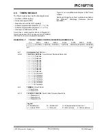
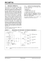
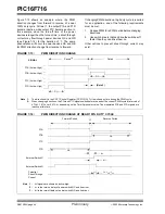
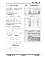
7.4.4
PROGRAMMABLE DEAD-BAND
DELAY
In half-bridge applications where all power switches are
modulated at the PWM frequency at all times, the
power switches normally require more time to turn off
than to turn on. If both the upper and lower power
switches are switched at the same time (one turned on,
and the other turned off), both switches may be on for
a short period of time until one switch completely turns
off. During this brief interval, a very high current (shoot-
through current) may flow through both power
switches, shorting the bridge supply. To avoid this
potentially destructive shoot-through current from
flowing during switching, turning on either of the power
switches is normally delayed to allow the other switch
to completely turn off.
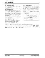
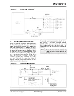
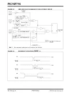
In the Half-Bridge Output mode, a digitally program-
mable dead-band delay is available to avoid shoot-
through current from destroying the bridge power
switches. The delay occurs at the signal transition from
the non-active state to the active state. See Figure 7-10
for illustration. The lower seven bits of the PWM1CON
register (Register 7-2) sets the delay period in terms of
microcontroller instruction cycles (T
CY
or 4 T
OSC
).
7.4.5
ENHANCED PWM
AUTO-SHUTDOWN
When the ECCP is programmed for any of the
enhanced PWM modes, the active output pins may be
configured for auto-shutdown. Auto-shutdown
immediately places the enhanced PWM output pins
into a defined shutdown state when a shutdown event
occurs.
A shutdown event can be caused by a logic low level on
either or both of the RB0/INT/ECCPAS2 or RB4/
ECCPAS0 pins. The auto-shutdown feature can be
disabled by not selecting any auto-shutdown sources.
The auto-shutdown sources to be used are selected
using the ECCPAS2 and ECCPAS0 bits (ECCPAS<6>
and ECCPAS<4>).
When a shutdown occurs, the output pins are
asynchronously placed in their shutdown states,
specified by the PSSAC1:PSSAC0 and
PSSBD1:PSSBD0 bits (ECCPAS<3:0>). Each pin pair
(P1A/P1C and P1B/P1D) may be set to drive high,
drive low, or be tri-stated (not driving). The ECCPASE
bit (ECCPAS<7>) is also set to hold the enhanced
PWM outputs in their shutdown states.
The ECCPASE bit is set by hardware when a shutdown
event occurs. If automatic restarts are not enabled, the
ECCPASE bit must be cleared by firmware when the
cause of the shutdown clears. If automatic restarts are
enabled, the ECCPASE bit is automatically cleared
when the cause of the auto-shutdown has cleared.
If the ECCPASE bit is set when a PWM period begins,
the PWM outputs remain in their shutdown state for that
entire PWM period. When the ECCPASE bit is cleared,
the PWM outputs will return to normal operation at the
beginning of the next PWM period.
Note:
Writing to the ECCPASE bit is disabled
while a shutdown condition is active.
Summary of Contents for PIC16F716
Page 6: ...PIC16F716 DS41206A page 4 Preliminary 2003 Microchip Technology Inc NOTES...
Page 35: ......
Page 56: ......
Page 60: ......
Page 88: ......
Page 92: ...PIC16F716 DS41206A page 90 Preliminary 2003 Microchip Technology Inc NOTES...
Page 108: ...PIC16F716 DS41206A page 106 Preliminary 2003 Microchip Technology Inc NOTES...
Page 110: ...PIC16F716 DS41206A page 108 Preliminary 2003 Microchip Technology Inc NOTES...
Page 124: ...PIC16F716 DS41206A page 122 Preliminary 2003 Microchip Technology Inc NOTES...


