


4.3
Data and Power Connection
Note:
This unit has no ON-OFF switch, simply plug the unit to a DC power source.
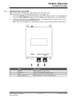
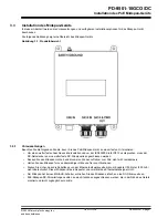
Follow the procedure to connect the data and power source to the midspan unit.
1.
Connect the
DATA IN
(input) jack from the midspan to remote Ethernet network (item 2 in the following figure).
2.
Connect the
DATA & PWR OUT
(output) jack from the midspan to the terminal (item 3 in the following figure).
3.
Connect DC power lines from the
LINE IN
terminal (item 1 in the following figure) to main DC power. Ensure
that the power outlet is nearby and easily accessible.
Note:
Connect the midspan unit to a weather-proof DC power source box that meets IP66 and IP67 ratings.
Label
Description
1
LINE IN
Power Input (12 V
DC
to 24 V
DC
)
2
DATA IN
Data In to the Ethernet (network) switch
3
DATA & PWR OUT
Data and power out to the Ethernet terminal
PD-9501-10GCO/DC
Installation of Cables
©
2022 Microchip Technology Inc.
and its subsidiaries
User Guide
DS50003347A-page 13


