background image

RFT9739 Rack-Mount Transmitter Instruction Manual

103

Appendix

F

Replacing Older Transmitters

Step 1  

Disconnecting the old transmitter

Follow these steps to wire the RFT9739 in place of the old transmitter:

a. Shut off power to the transmitter.

b. Open the transmitter wiring compartment covers. 

Do not disconnect 

wires from the transmitter yet. 

Wires will need to be moved from 

the old transmitter terminals to the appropriate terminals on the 
RFT9739 transmitter. Make note of which terminals the wires are 
connected to 

before removing them from the old transmitter.

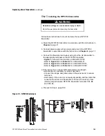
• Figure F-1 shows the location of terminals on a Model RFT9739
• Figure F-2 shows the location of terminals on a Model RE-01
• Figure F-3 shows the location of terminals on a Model RFT9712

c. Detach wires from the old transmitter, then remove the transmitter.

d. Proceed to Step 2, page 104.

WARNING

Hazardous voltage can cause severe injury or death.

Shut off power before disconnecting the transmitter.

CAUTION

Process control will stop when the transmitter is 
disconnected.

Set control devices for manual operation before 
disconnecting the transmitter.

Summary of Contents for Fisher Rosemount RFT9739

Page 1: ...Model RFT9739 Rack Mount Transmitter Instruction Manual Version 3 Transmitters February 2000 ...

Page 2: ......

Page 3: ...tion Inc All rights reserved Micro Motion ELITE and ProLink are registered trademarks of Micro Motion Inc Boulder Colorado Rosemount and SMART FAMILY are registered trademarks of Rosemount Inc Eden Prairie Minnesota Fisher Rosemount is a trademark of Fisher Rosemount Clayton Missouri HART is a registered trademark of the HART Communication Foundation Austin Texas Modbus is a registered trademark o...

Page 4: ......

Page 5: ...characterization 4 2 3 Switch settings 5 Security modes 6 Security mode 8 7 Communication settings 9 Milliamp output scaling 9 3 Transmitter Mounting 11 3 1 General guidelines 11 3 2 Connectors 15 4 Power Supply and Sensor Wiring 17 4 1 General guidelines 17 4 2 Power supply and grounding 17 Power supply options 17 Power supply wiring 18 Grounding 19 Fuses 21 4 3 Changing power supply voltage 21 4...

Page 6: ...Setting voltage level for VDE output requirements 37 Optocoupler output 39 5 5 Control output 40 Control output in open collector mode 41 5 6 Peripheral device wiring 44 5 7 Pressure transmitter wiring 51 5 8 Remote zero switch 54 5 9 RS 485 multidrop network 55 5 10 Bell 202 multidrop network 56 5 11 Security wiring 58 6 Startup 59 6 1 Initialization 59 6 2 Using the display 60 Process variables ...

Page 7: ...es 73 Overrange and sensor error messages 74 Slug flow 74 Output saturated messages 74 Informational messages 76 7 5 Power supply 77 7 6 Wiring 78 7 7 Master reset 79 7 8 Additional information about troubleshooting 81 7 9 Customer service 81 Appendixes Appendix A RFT9739 Specifications 83 Appendix B Ordering Information 91 Appendix C Theory of Operation 93 Appendix D HART Communicator Menu Trees ...

Page 8: ...eroing 66 Table 6 2 Effect of security modes on totalizer control 68 Table 7 1 Fault output levels 69 Table 7 2 Using transmitter failure messages 73 Table 7 3 Using overrange and sensor error messages 75 Table 7 4 Using slug flow and output saturated messages 75 Table 7 5 Using informational messages 77 Table 7 6 Nominal resistance ranges for flowmeter circuits 78 Table 7 7 Default values after a...

Page 9: ...ing 31 Figure 5 6 Frequency pulse output wiring for increased current 31 Figure 5 7 Frequency pulse output wiring for constant current 32 Figure 5 8 Frequency pulse output wiring for open collector mode 34 Figure 5 9 RFT9739 back panel 34 Figure 5 10 Resistor R5 on inside of back panel 35 Figure 5 11 Dual channel frequency output wiring 36 Figure 5 12 RFT9739 back panel and power board 37 Figure 5...

Page 10: ...h 54 Figure 5 29 RS 485 wiring 56 Figure 5 30 Typical HART network wiring 57 Figure 5 31 Inhibit switch wiring 58 Figure 7 1 HART Communicator ProLink PC Interface and AMS modem connections 71 Figures in appendixes Figure C 1 Coriolis mass flow sensor 93 Figure D 1 On line menu 97 Figure E 1 RFT9739 back panels 101 Figure F 1 RFT9739 terminals 105 Figure F 2 RE 01 Remote Electronics Unit terminals...

Page 11: ... Motion rack mount transmitters have enhanced EMI immunity that complies with EMC directive 89 336 EEC and low voltage directive 73 23 EEC when properly installed in accordance with the guidelines and instructions in this manual The Model RFT9739 transmitter is a microprocessor based transmitter for fluid process measurement The transmitter works with Micro Motion sensors to measure mass or volume...

Page 12: ...Rack Mount Transmitter Instruction Manual Before You Begin continued Figure 1 1 RFT9739 exploded view Module cassette Control board Top cover Back panel Power board Side panel Bottom cover Front panel Side panel ...

Page 13: ...ctions In Europe refer to standard EN60079 14 if national standards do not apply To comply with CENELEC standards see page 4 The RFT9739 rack mount transmitter is classified as a Class A product When used in a residential area or in an adjacent area thereto radio interference may be caused by radios television receivers and like devices Figure 2 1 Hazardous area approvals tag WARNING If the sensor...

Page 14: ...cessary Configuration parameters include items such as transmitter tag measurement units flow direction damping values slug flow parameters and span values for the milliamp and frequency outputs If requested at time of order the transmitter is configured at the factory according to customer specifications Calibration accounts for an individual sensor s sensitivity to flow density and temperature F...

Page 15: ...ns see Figure 1 1 page 2 for the location of the control board Communications settings including baud rate stop bits and parity data bits communication protocol and physical layer mA outputs Zeroing method Write protection of transmitter configuration Switches are shown in Figure 2 2 and described in the following sections To access switches remove the bottom cover of the transmitter housing Norma...

Page 16: ...s 1 through 7 are entered immediately when switches are set For information about security mode 8 see pages 7 through 8 Table 2 1 Security modes Switch settings Mode 1 Mode 2 Mode 3 Mode 4 Mode 5 Mode 6 Mode 7 Mode 8 Changing the settings of switches 1 2 and 3 does not immediately implement security mode 8 For more information about security mode 8 see pages 7 through 8 Switch 1 Switch 2 Switch 3 ...

Page 17: ...until the transmitter is reconfigured for security mode 8 or until a master reset has been performed Custody transfer event registers are not affected by a master reset For information about event registers see Section 6 3 page 64 To perform a master reset see Section 7 7 page 79 Milliamp output trim milliamp output test and frequency pulse output test procedures cannot be performed after security...

Page 18: ... Motion Transmitters Using ProLink Software with Micro Motion Transmitters Using Modbus Protocol with Micro Motion Transmitters 3 Set switches 1 2 and 3 to the ON position To reenter security mode 8 If security mode 8 has been established previously and the security mode has been temporarily changed it is not necessary to use the Reset button to reenter security mode 8 In such a case resetting swi...

Page 19: ...bits and parity data bits protocol and physical layer When the transmitter is shipped from the factory the default settings are HART protocol over RS 485 at 1200 baud with 1 stop bit and odd parity For more information on using the display see Section 6 2 page 60 Milliamp output scaling Switches 7 8 and 9 allow the user to choose 0 20 mA or 4 20 mA scaling for mA outputs and upscale or downscale f...

Page 20: ...10 RFT9739 Rack Mount Transmitter Instruction Manual ...

Page 21: ...00 feet 300 meters Locate the transmitter where the ambient temperature remains between 32 and 122 F 0 and 50 C The rack mount RFT9739 meets DIN standard 41494 19 inch configuration for control room equipment Transmitter dimensions are shown in Figure 3 1 page 12 Three transmitters fit into one 19 inch enclosure with a Eurocard 220 mm depth as indicated in Figure 3 2 page 13 When installing multip...

Page 22: ...2 66 13TE 4 13 16 122 4 2 19 32 66 13TE 5 37 64 141 7 28TE 5 127 25TE 5 3 64 128 4 3HE 8 23 64 212 3 3 16 4 7 47 64 18 7 9 15 64 234 6 4 3 8 111 1 With Y shaped screw terminals With fast on solder terminals 10 5 16 281 9 10 1 16 255 6 Back panel with DIN 41612 male Y shaped screw terminals Back panel with DIN 41612 male fast on solder terminals 4X M2 5 x 11 ...

Page 23: ...ng Startup Troubleshooting Before You Begin Getting Started Mounting Power Supply and Sensor Wiring Figure 3 2 Rack mount connector locations 0TE 6TE CN1 34TE CN1 47TE CN2 62TE CN1 75TE CN2 84TE 5 37 64 141 7 28TE 19 483 8 13 32 213 5 19TE CN2 Dimensions in inches mm 1 TE 5 08 mm 5 3 64 128 4 3HE ...

Page 24: ...proper ventilation 5 3 64 128 4 3HE 1 22 32 42 8 1HE 5 3 64 128 4 3HE 1 22 32 42 8 1HE 5 3 64 128 4 3HE Dimensions in inches mm When installing multiple transmitters in a single rack 15 watts of forced air cooling per transmitter is required Maintain sufficient air flow to keep the ambient temperature below 122 F 50 C ...

Page 25: ...nects to CN1 Output wiring connects to CN2 Connectors CN1 and CN2 are available in two types illustrated in Figure 3 4 page 15 The standard rectangular configuration accommodates fast on wire pin or soldered connections The optional Y shaped connectors have screw terminals which accommodate wires as large as 14 AWG 2 5 mm For fast on solder connectors on connector CN1 pin row D is not used on conn...

Page 26: ...16 RFT9739 Rack Mount Transmitter Instruction Manual ...

Page 27: ...upper corner on the transmitter s back panel indicates the configured power supply voltage See Figure 4 1 page 18 Any RFT9739 rack mount transmitter can accept a DC power supply whether or not the back panel indicates the transmitter has been configured for AC power To change power supply voltage from the configured voltage see Section 4 3 page 21 WARNING Failure to comply with requirements for in...

Page 28: ... 318 549 443 To install power supply wiring refer to Figure 4 1 and follow these steps 1 Match power supply voltage to voltage indicated on the label in the upper corner of the transmitter back panel 2 Connect AC power supply wiring at connector CN3 and the ground lug directly above connector CN3 or connect DC power supply wiring at connector CN2 to terminals Z32 DC and D32 DC 3 Ground the transmi...

Page 29: ...ition Figure Page Sensor is installed in a non hazardous area 4 2a 19 Sensor is installed in hazardous area plant does not have a separate intrinsically safe ground system installations in Europe only 4 2a 19 Sensor is installed in a hazardous area any area except Europe 4 2b 20 Plant uses a separate high integrity I S ground scheme 4 2c 20 Ground wire Earth ground If national standards are not in...

Page 30: ...ply ground directly to earth High integrity I S ground Earth ground If national standards are not in effect adhere to these guidelines for grounding Use copper wire 14 AWG 2 5 mm or larger wire size Keep all ground leads as short as possible less than 1 ohm impedance A factory installed ground wire connecting the I S ground and power supply ground terminals must be removed Connect ground lead from...

Page 31: ...ure 4 3 page 21 4 3 Changing power supply voltage A switch labeled S1 located inside the transmitter on the power board see Figure 4 3 allows the AC power supply voltage to be changed When switching from AC to DC power 1 Remove the AC power wiring 2 Properly install the DC wiring When switching AC voltage or when switching from DC to AC power 1 Turn off power then detach the existing power supply ...

Page 32: ...he terminal blocks No bare wires should remain exposed At the sensor connect wiring inside the sensor junction box At the transmitter connect wiring to the transmitter s intrinsically safe sensor terminals for sensor wiring as numbered in Table 4 2 page 23 The transmitter terminal block can be unplugged for easier connection of wiring 2 Locate the wires by color as indicated in Table 4 2 page 23 3...

Page 33: ...Brown Black Drains Violet Green Blue B2 B4 B6 B8 B10 Z2 Z4 Z6 Z8 Z10 Brown Red Clip drain wire back Green White Clip drain wire back Blue Gray Clip drain wire back Orange Violet Yellow Clip drain wire back Flowmeter cable Brown Red Green White Blue Gray Orange Violet Yellow Black Drains from all wire sets Maximum cable length 1000 ft 300 m Prepare cable in accordance with the instructions that are...

Page 34: ...Clip drain wire back Orange Violet Yellow Clip drain wire back Flowmeter cable Brown Red Green White Blue Gray Orange Violet Yellow Black Drains from all wire sets Maximum cable length 1000 ft 300 m Prepare cable in accordance with the instructions that are shipped with the cable Brown Red Orange Yellow Green Blue Violet Gray White Sensor wire number 1 2 3 4 5 6 7 8 9 Earth ground Red Yellow Orang...

Page 35: ...sically safe connections between the RFT9739 and other devices may only be made to devices that maintain a voltage less than or equal to 250 V 5 2 Maximum wire length Currently there is no system for accurately estimating the maximum length of wire between the RFT9739 and a connected peripheral device Most applications will be able to use wire lengths up to 500 feet for 22 AWG wire 150 meters for ...

Page 36: ...uency output channel A D14 and Z14 Signal ground D16 and D14 Scroll inhibit Z12 and D26 Dual channel quadrature frequency output channel B D18 and D14 Zero inhibit D20 and D26 Remote zero input Z16 and Z14 Tube period output D22 and Z22 RS 485 I O Z18 and Z14 Temperature output D24 and D26 Frequency pulse output Z20 mA input from pressure or DP transmitter D28 and Z28 Secondary variable SV mA outp...

Page 37: ...oop powered process indicators For transmitters with software version 3 8 or higher when configured to produce 4 20 mA current the mA outputs are compliant with the NAMUR NE43 standard All RFT9739 transmitters shipped after November 1999 have software version 3 8 or higher In compliance with the NAMUR NE43 standard 4 20 mA outputs will produce a live signal from 3 8 to 20 5 mA 4 20 mA outputs will...

Page 38: ... either at the transmitter end or at the external device The maximum allowable length for mA signal wiring is determined by measuring resistance over the signal wires and through the receiver device Total loop resistance must not exceed 1000 ohms The primary mA output must be set to the 4 20 mA mode for the Bell 202 physical layer The Bell 202 layer will not work with the primary mA output configu...

Page 39: ... devices require a minimum loop resistance of 250 ohms Loop resistance must not exceed 1000 ohms regardless of the communication setup 2 The DCS or PLC must be configured for an active milliamp signal 3 Resistor R3 is required if the DCS or PLC does not have an internal resistor CAUTION Connecting a HART device to the RFT9739 primary variable milliamp output loop could cause transmitter output err...

Page 40: ...DE output requirements page 37 Output impedance is 2 2 kohm For use with receivers other than Micro Motion peripheral devices check the instruction manual for the receiver to make sure its input voltage and electrical current ratings match the RFT9739 ratings Frequency pulse output The frequency pulse output represents the flow rate independent of the primary and secondary mA outputs The frequency...

Page 41: ...proximately 7 mA See Figure 5 5 Figure 5 5 Frequency pulse output wiring Configuration for increased current In some applications it might be necessary to increase the current in the frequency pulse output circuit See Section 5 2 page 25 For increased current to the circuit add a 1 to 3 kohm resistor across terminals CN2 Z26 and CN2 D24 as illustrated in Figure 5 6 Figure 5 6 Frequency pulse outpu...

Page 42: ...unction properly independent of this frequency pulse wiring procedure See Control output in open collector mode page 41 The optocoupler and dual channel frequency outputs could be affected by configuring the frequency pulse output for constant current as described above To reduce this risk use a 250 ohm resistor as indicated in Figure 5 7 Figure 5 7 Frequency pulse output wiring for constant curre...

Page 43: ...tance at the transmitter To prevent damage to the optocoupler and dual channel frequency output circuits the external voltage must not exceed 15 V Resistor R5 is located on the inside of the RFT9739 back panel To access resistor R5 refer to Figure 5 9 page 34 and follow these steps 1 Remove the bottom cover of the transmitter housing 2 Remove the back panel and carefully pull it loose from the pow...

Page 44: ...wiring for open collector mode Figure 5 9 RFT9739 back panel Resistor must be of sufficient value to limit loop current to less than 0 1 ampere depending on total loop resistance PLC or pulse counter RFT9739 output terminals Resistor See note DC power supply FREQ signal line RETURN ground Back panel Bottom cover ...

Page 45: ...ack Mount Transmitter Instruction Manual 35 Output Wiring Startup Troubleshooting Before You Begin Getting Started Mounting Power Supply and Sensor Wiring Figure 5 10 Resistor R5 on inside of back panel Inside of back panel Resistor R5 ...

Page 46: ...e output For example if the frequency pulse output is 4 000 Hz each dual channel output is 2 000 Hz The phase shift between channels is 90 degrees Use RFT9739 terminals CN2 Z10 CN2 Z12 and CN2 D26 for the dual channel frequency output Terminal D26 serves as a common return for the dual channel frequency output frequency pulse output control output and remote zero input See Figure 5 11 Figure 5 11 ...

Page 47: ...umper JP1 on the inside of the back panel which is illustrated in Figure 5 14 page 38 4 Both jumpers are labeled to show a position for standard 15 volt operation STD and 30 V operation VDE to meet VDE output requirements Set both jumpers to the same position With the jumper on the center pin and the pin labeled VDE the output is set for 30 volts Set the output to the VDE position to meet VDE outp...

Page 48: ...nsmitter Instruction Manual Output Wiring continued Figure 5 13 Jumper J10 on power board Figure 5 14 Jumper JP1 on inside of back panel Power board Jumper J10 Inside of back panel Jumper JP1 Area of detail Detail of back panel ...

Page 49: ...output is derived from the primary frequency output and represents the same flow rate variable as the frequency pulse output Use RFT9739 terminals CN2 D10 CN2 D12 and CN2 D4 for the optocoupler output Figure 5 15 illustrates the wiring connection from the optocoupler output to an auxiliary device Signal voltage is 0 2 VDC low 16 30 VDC high with a 0 01 ampere maximum sinking capability Figure 5 15...

Page 50: ...te flow direction the output is high 15 VDC when indicating forward flow and low 0 VDC when indicating reverse flow When configured to indicate transmitter zeroing in progress the output is low 0 VDC when zeroing is in progress and high 15 VDC at all other times When configured to indicate faults the output is low 0 VDC when a fault condition exists and high 15 VDC during normal operation When con...

Page 51: ...pull up resistor See Figure 5 17 page 42 The pull up resistor must be of sufficient value to limit loop current to less than 0 1 ampere depending on the total loop resistance at the transmitter To prevent damage to the optocoupler and dual channel frequency output circuits the external voltage must not exceed 15 V Resistor R4 is located on the inside of the RFT9739 back panel To access resistor R4...

Page 52: ...ng for open collector mode Figure 5 18 RFT9739 back panel Resistor must be of sufficient value to limit loop current to less than 0 1 ampere depending on total loop resistance Receiving device RFT9739 output terminals Resistor See note DC power supply RETURN ground CONTROL signal line Back panel Bottom cover ...

Page 53: ...unt Transmitter Instruction Manual 43 Output Wiring Startup Troubleshooting Before You Begin Getting Started Mounting Power Supply and Sensor Wiring Figure 5 19 Location of resistor R4 on inside of back panel Inside of back panel Resistor R4 ...

Page 54: ...display 5 21a 45 DRT Digital Rate Totalizer with LCD display 5 21b 45 FMS 3 Flow Monitoring System with LED display 5 22a 46 FMS 3 Flow Monitoring System with LCD display 5 22b 46 NFC Net Flow Computer 5 23 47 NOC Net Oil Computer with AC power supply 5 24a 48 NOC Net Oil Computer with DC power supply 5 24b 48 Model 3300 Discrete Controller with screw solder terminals 5 25a 49 Model 3300 Discrete ...

Page 55: ...ting Before You Begin Getting Started Mounting Power Supply and Sensor Wiring Figure 5 21a Wiring to DRT with LED Figure 5 21b Wiring to DRT with LCD RFT9739 output terminals DRT LED terminals Earth ground Clip shields at this end RFT9739 output terminals DRT LCD terminals Earth ground Clip shields at this end ...

Page 56: ...t Wiring continued Figure 5 22a Wiring to FMS 3 with LED Figure 5 22b Wiring to FMS 3 with LCD RFT9739 output terminals FMS 3 LED terminals Earth ground Clip shields at this end RFT9739 output terminals FMS 3 LCD terminals Earth ground Clip shields at this end ...

Page 57: ... Output Wiring Startup Troubleshooting Before You Begin Getting Started Mounting Power Supply and Sensor Wiring Figure 5 23 Wiring to NFC 1 Clip shields at this end 2 This wire not terminated RFT9739 output terminals NFC terminals Note 1 Note 1 Note 2 Note 2 Earth ground Note 1 ...

Page 58: ... NOC Figure 5 24b Wiring to DC powered NOC 1 Clip shields at this end 2 This wire not terminated RFT9739 output terminals NOC terminals Earth ground Note 1 Note 1 Note 1 Note 2 Note 2 1 Clip shields at this end 2 This wire not terminated RFT9739 output terminals NOC terminals Note 1 Note 1 Note 2 Note 2 Note 1 ...

Page 59: ...Begin Getting Started Mounting Power Supply and Sensor Wiring Figure 5 25a Wiring to Model 3300 with screw type or solder tail terminals Figure 5 25b Wiring to Model 3300 with I O cable RFT9739 output terminals Model 3300 terminals Clip shields at this end RFT9739 output terminals Model 3300 terminals Clip shields at this end ...

Page 60: ...50 RFT9739 Rack Mount Transmitter Instruction Manual Output Wiring continued Figure 5 26 Wiring to Model 3350 RFT9739 output terminals Model 3350 terminals Clip shields at this end ...

Page 61: ...e RFT9739 pressure input terminals CN2 Z6 and CN2 Z20 are intended for use with a pressure transmitter and should not be connected to a control system If the RFT9739 is configured for pressure compensation flowmeter measurement will not be compensated for pressure during a pressure input failure If the signal from the pressure transmitter fails both of the following occur The RFT9739 continues to ...

Page 62: ... greater than 11 75 V or if other loop devices are required an external source can power the pressure transmitter Use RFT9739 terminals CN2 Z20 and CN2 D14 or CN2 Z14 Terminal Z20 S is the signal input to the RFT9739 and terminal D14 or Z14 SIGNAL GND is the return as shown in Figure 5 27b page 53 If digital communication between the pressure transmitter and the RFT9739 is required use primary var...

Page 63: ...pressure transmitter digital communications Pressure transmitter WARNING Pressure transmitter wiring is not intrinsically safe Power supply 24 VDC 4 20 mA Optional loop device s RFT9739 output terminals Terminal CN2 D14 must be connected directly to the negative terminal of the external power supply Pressure transmitter SMART only 1150 or 3051 WARNING Pressure transmitter wiring is not intrinsical...

Page 64: ...er zeroing procedure Section 6 5 page 67 describes the totalizer reset procedure The switch must be a momentary type contact normally open close to zero and must carry 1 mA of current in the closed position The open circuit voltage is 5 VDC Use terminals CN2 D20 and CN2 D26 for the remote switch Terminal D26 serves as a common return for the external switch input frequency pulse output dual channe...

Page 65: ... unique tag name If polling addresses are used up to 16 transmitters can have unique polling addresses from 0 to 15 Under Modbus protocol up to 15 transmitters can participate in the network Each transmitter must have a unique polling address from 1 to 15 To connect the transmitter to an RS 485 network use transmitter terminals CN2 Z22 and CN2 D22 Figure 5 29 page 56 shows how to connect one RFT97...

Page 66: ...compatible network A Bell 202 multidrop network uses twisted pair wire and allows only digital communication Digital communication requires a sample rate of 2 to 31 seconds at 1200 baud A HART Communicator or other HART compatible control system can communicate with any device in the network over the same 2 wire pair Using multiple transmitters in a HART compatible network requires assigning a uni...

Page 67: ...ed 1000 ohms Connect the mA outputs from each transmitter together so they terminate at a common load resistor with at least 250 ohms impedance installed in series Figure 5 30 Typical HART network wiring PV 17 PV 18 PV CN2 Z30 PV CN2 D30 4 20mA 4 20mA 24 DC For optimum HART communication make sure the output loop is single point grounded to instrument grade ground HART Communicator ProLink PCI or ...

Page 68: ...button connect a signal line to terminal CN2 D16 SCROLL INH and a ground wire to terminal CN2 D14 SIGNAL GND See Figure 5 31 Reset inhibit To install a remote key switch that disables the front panel Reset button connect a signal line to terminal CN2 D18 ZERO INH and a ground wire to terminal CN2 D14 SIGNAL GND See Figure 5 31 Figure 5 31 Inhibit switch wiring RFT9739 output terminals SCROLL INH s...

Page 69: ...of inrush current at a minimum of 12 volts at the transmitter s power input terminals If the startup voltage is pulled below 12 VDC the transmitter could remain in the startup loop indefinitely After the self test is complete one of 10 possible process variable screens such as the one depicted below displays If the flowmeter is operating properly the blinking Msg message indicator appears in the b...

Page 70: ... a process variable As the user scrolls through the process variable screens they appear in the order listed in Table 6 1 Table 6 1 Display screens Screen Process variable Abbreviation in upper left corner of screen 1 Mass flow rate RATE 2 Volume flow rate RATE 3 Density DENS 4 Temperature TEMP 5 Mass total 1 1 While reading total TOT or inventory INV screens use the unit of measure in the lower l...

Page 71: ...roll past the message screen to the flow rate screen If power to the transmitter has been cycled and the transmitter is operating properly the message reads Sensor OK POWER RESET For more information about messages refer to Section 7 4 page 73 Communication configuration mode Switch 5 on the transmitter control board allows the user to select the standard communication configuration or establish a...

Page 72: ...iew each stop bit S option Choose 1 stop bit or 2 stop bits 2 Press and hold the Reset button to select the displayed stop bit Release the Reset button when the display stops flashing 3 When the selected stop bit flashes again press and release the Reset button to move to the parity P options 4 Press and release the Scroll button to view each parity P option Choose from odd parity O even parity E ...

Page 73: ...s again press and release the Reset button to move to the protocol and physical layer options 4 Press and release the Scroll button to view each protocol physical layer option Choose from the following HART protocol over the Bell 202 physical layer HART 202 HART protocol over the RS 485 physical layer HART 485 Modbus protocol over the RS 485 physical layer Modbus 485 Modbus protocol over the RS 48...

Page 74: ... be reset View the security event registers using any of the following methods With the RFT9739 display If the transmitter has a display event registers can be viewed from the CONFIG REG and CALIBRATE REG screens when the transmitter is configured for security mode 8 With ProLink software version 2 3 or higher Refer to on line help for instructions With AMS software Refer to on line help for instr...

Page 75: ...rating temperature 2 Close the shutoff valve downstream from the sensor 3 Ensure zero flow through the sensor 4 Zero the transmitter in any of four ways Press and hold the Reset button for at least ten seconds In the rate screens RATE appears in the upper left corner of the screen An external contact closure can be used for transmitter zeroing Refer to Section 5 8 page 54 for wiring instructions C...

Page 76: ... are filled with fluid and flow is stopped then re zero the flowmeter again Additional information about flowmeter zeroing Flowmeter zeroing can be disabled using the transmitter s security modes or with a remote keyed switch that disables the RFT9739 Reset button Table 6 1 describes how RFT9739 security modes 1 through 8 affect flowmeter zeroing Refer to Section 2 3 page 5 for more information ab...

Page 77: ...page 58 describes how to install keyed switches to disable the front panel Scroll and Reset buttons Mass and volume totalizers cannot be reset independently When one totalizer is reset the other is also reset Resetting the totalizer has no effect on the mass or volume inventory To reset the transmitter s mass totalizer and volume totalizer using the RFT9739 Scroll and Reset buttons 1 Use the Scrol...

Page 78: ...ormed with Mode 1 Mode 2 Mode 3 Mode 4 Mode 5 Mode 6 Mode 7 Mode 8 No flow Scroll and Reset buttons Disabled Disabled Disabled Disabled HART or Modbus device Disabled Disabled Disabled With flow Scroll and Reset buttons Disabled Disabled Disabled Disabled Disabled Disabled Disabled HART or Modbus device Disabled Disabled Disabled Disabled Disabled Disabled Resetting the totalizer has no effect on ...

Page 79: ...or operates Check all signals under both flow and no flow conditions This procedure will minimize the possibility of overlooking some causes or symptoms 7 2 Transmitter diagnostic tools In some situations troubleshooting requires use of the transmitter s diagnostic tools which include fault output levels and diagnostic messages Fault outputs The RFT9739 has downscale and upscale fault outputs See ...

Page 80: ...tion 7 4 page 73 Modbus host controllers use status bits as diagnostic messages In the event of a display readback failure if the error does not clear itself within 60 seconds cycle power to the transmitter turn power OFF then ON 7 3 Interrogation with a HART device Connect a HART device to the communications socket on the transmitter front panel the socket is labeled HART or use the ProLink progr...

Page 81: ...ignal 3 Resistor R3 is required if the DCS or PLC does not have an internal resistor CAUTION Connecting a HART device to the RFT9739 primary variable milliamp output loop could cause transmitter output error If the primary variable PV analog output is being used for flow control connecting a HART device to the output loop could cause the transmitter 4 20 mA output to change which would affect flow...

Page 82: ...ming an mA output test forces the transmitter to produce a user specified current output of 0 to 22 mA Performing a frequency pulse output test forces the transmitter to produce a user specified frequency output between 0 1 and 15 000 Hz Performing an mA output trim allows adjustment of the primary and secondary mA outputs against a highly accurate external standard such as a digital multimeter DM...

Page 83: ...wing messages Xmtr Failed E eprom Error RAM Error RTI Error If a transmitter failure occurs contact the Micro Motion Customer Service Department Table 7 2 describes transmitter failure messages CAUTION Transmitter failures are critical and could cause unintentional switching of process control devices The transmitter does not have any parts that are serviceable by the user If a transmitter failure...

Page 84: ...turn causes the transmitter to produce inaccurate flow signals If the user programs slug limits a slug flow condition causes the following to occur 1 The message display reads SLUG FLOW 2 The frequency pulse output goes to 0 Hz 3 The mA outputs indicating the flow rate go to the level that represents zero flow The flowmeter resumes normal operation when liquid fills the flow tubes and density stab...

Page 85: ...oisture in sensor case Replace conduit and or conduit seals Repair cable Return sensor to Micro Motion Drive Overrng or Dens Overrng Transmitter produces fault outputs Inappropriate density factors Process density 5 0000 g cc Severely erratic or complete cessation of flow tube vibration due to gas slugs or solids in process fluid Plugged flow tube Calibrate for density Correct density factors Moni...

Page 86: ...tocol In burst mode the transmitter bursts data at regular intervals mA 1 Fixed or mA 2 Fixed indicates one of several conditions The mA output trim or test was not completed The output remains fixed at the assigned level until the user completes the output trim or test procedure The user has assigned a polling address other than 0 to the transmitter for Bell 202 communication The output remains f...

Page 87: ...er Reset Power failure Brownout Power cycling Check accuracy of totalizers Cal in Progress Flowmeter zeroing in progress Density calibration in progress If Cal in Progress disappears no action If Cal in Progress reappears after zeroing or calibration is completed Check flowmeter cable Eliminate noise then rezero or recalibrate Zero Too Noisy Mechanical noise prevented accurate zero flow setting du...

Page 88: ...CN1 Z10 and CN1 B10 blue gray RTD check terminals CN1 Z6 and CN1 B4 violet yellow 4 If the measured resistance is outside the range listed in Table 7 6 repeat the measurements at the sensor terminals 5 Reinsert the terminal blocks and restore power to the transmitter 6 Use the DMM to troubleshoot the flowmeter Table 7 6 Nominal resistance ranges for flowmeter circuits Notes Temperature sensor valu...

Page 89: ...inal position 8 Shut off power to the transmitter Wait 30 seconds 9 Restore power If switches are left in the ON position another master reset will occur the next time power to the transmitter is shut off and then restored To avoid an unintentional master reset set switches 4 6 and 10 to the OFF position after performing a master reset After the user performs a master reset the blinking Msg indica...

Page 90: ... Forward only Internal damping on density 2 00 sec Internal damping on flow 0 80 sec Internal damping on temperature 4 00 sec Transmitter output variables Default Default Primary mA output variable Mass flow Frequency pulse output variable Mass flow Upper range value 160 00 g sec Frequency 10000 00 Hz Lower range value 160 00 g sec Rate 15000 00 g sec Added damping 0 00 sec Maximum pulse width 0 5...

Page 91: ...739 transmitter see any of the following instruction manuals or AMS on line help Using the HART Communicator with Micro Motion Transmitters Using ProLink Software with Micro Motion Transmitters Using Modbus Protocol with Micro Motion Transmitters 7 9 Customer service For technical assistance phone the Micro Motion Customer Service Department In the U S A phone 1 800 522 6277 24 hours Outside the U...

Page 92: ...82 RFT9739 Rack Mount Transmitter Instruction Manual ...

Page 93: ...id 0 05 zero stability flow rate x 100 of rate gas 0 30 zero stability flow rate x 100 of rate DH38 liquid 0 05 zero stability flow rate x 100 of rate gas 0 25 zero stability flow rate x 100 of rate Sensor model Density accuracy Density repeatability g cc kg m3 g cc kg m3 ELITE except CMF010P liquid only 0 0005 0 5 0 0002 0 2 ELITE CMF010P liquid only 0 002 2 0 0 001 1 0 F Series liquid only 0 002...

Page 94: ...000 kg m Minimum span 0 05 g cc 50 kg m Temperature Range limit 400 to 842 F 240 to 450 C Minimum span 36 F 20 C Frequency One frequency pulse output can be configured to indicate mass flow rate volumetric flow rate mass total inventory or volume total inventory independent of analog outputs Internally powered 0 15 V square wave unloaded 2 2 kohm impedance at 15 V galvanically isolated to 50 VDC I...

Page 95: ...n Switch allows selection of preset or user defined settings Default preset settings HART protocol over Bell 202 on the primary mA output 1200 baud Modbus protocol in RTU mode on the RS 485 output 9600 baud 1 stop bit odd parity Default user defined settings HART protocol on the RS 485 output 1200 baud 1 stop bit odd parity Bell 202 signal is superimposed on primary variable mA output and availabl...

Page 96: ... rate is typically attainable for Generalized Petroleum Products such as fuel oils jet fuels and kerosenes Pressure compensation The analog input can accept a signal from a pressure transmitter for pressure compensation of flow and density Range 0 25 mA Can be used to power independent pressure or differential pressure transmitter Voltage sourcing capability 15 V Input impedance 100 ohms Low flow ...

Page 97: ...o reset the transmitter s flow totalizers and communication parameters and perform the flowmeter zeroing procedure Power supply options and fuses 110 115 VAC 25 48 to 62 Hz 10 watts typical 15 watts maximum fused with UL CSA 250mA 250V time lag 5x20mm 220 230 VAC 25 48 to 62 Hz 10 watts typical 15 watts maximum fused with UL CSA 250mA 250V time lag 5x20mm All AC powered RFT9739 transmitters comply...

Page 98: ...cro Motion sensor and the sensor cable must be either doubly shielded with full contact glands or installed in continuous fully bonded metallic conduit The transmitter and sensor must be directly connected to a low impedance less than 1 ohm earth ground Transmitter outputs must be run in standard twisted pair shielded instrument wire Ambient temperature effect on transmitter On mA outputs 0 005 of...

Page 99: ...ck European standard DIN 41494 128 mm 3HE high x 142 mm 28TE wide x 231 9 mm deep Electrical connections Two connectors per DIN 41612 type F Choose either fast on wire pin solder connectors standard or Y shaped screw terminal connectors optional Sensor connectors and output connectors are not interchangeable Weight 4 4 lb 2 0 kg ...

Page 100: ...90 RFT9739 Rack Mount Transmitter Instruction Manual ...

Page 101: ... 220 230 VAC 3 12 to 30 VDC Code Configuration E Enhanced EMI immunity CE compliant requires installation with Micro Motion cable type CPLTJ or CFEPJ installed in conduit or type CPLTS CPLTA CFEPS or CFEPA installed with approved cable glands Code Approval M Micro Motion standard no approvals U UL intrinsically safe C CSA B CENELEC intrinsically safe sensor outputs Code Glands F Fast on solder ter...

Page 102: ...tter Instruction Manual Communications Using ProLink Software with Micro Motion Transmitters Using the HART Communicator with Micro Motion Transmitters Using Modbus Protocol with Micro Motion Transmitters RFT9739 Transmitter Specific Command Specification RFT9709 Transmitter Specific Command Specification RFT9712 Transmitter Specific Command Specification Peripheral products DMS Density Monitoring...

Page 103: ... the apex of the bent tubes see Figure C 1 An AC drive control amplifier circuit in the transmitter reinforces the signal from the sensor s left velocity pickoff coil to generate the drive coil voltage The amplitude of this drive coil voltage is continuously adjusted by the circuit to maintain a constant low amplitude of flow tube displacement minimizing stress to the tube assembly Figure C 1 Cori...

Page 104: ...er is converted to a frequency and is digitized by a counter read by the microprocessor Density measurement The Coriolis mass flow sensor also functions as a vibrating tube density meter The natural frequency of the tube assembly is a function of tube stiffness tube geometry and the mass of the fluid the tube contains Therefore fluid density can be derived from a measurement of tube frequency The ...

Page 105: ...for Generalized Petroleum Products from 2 to 95 API over an operating temperature range of 0 to 300 F As fluid density or operating temperature extends beyond these values the RFT9739 correlation error will increase Density calibration must be performed in units of g cc for the API correlation to be correct API standard volume If API is selected as the density unit the RFT9739 automatically calcul...

Page 106: ...an isolated 4 20 or 0 20 mA signal over either of two sets of output terminals Alternatively either mA output can be configured to indicate temperature density pressure event 1 or event 2 Mass or volume flow pulses from the isolated frequency output terminals can be scaled to 10 000 Hz for compatibility with PLCs batch controllers and totalizers All measured variables including totalizers for batc...

Page 107: ...PUT VARIABLES 3 View status 1 Mass total 2 Volume total 3 Start totalizer 4 Stop totalizer 5 Reset totalizer 4 TOTALIZER CONTROL 1 View status 2 Self test 1 TEST STATUS 2 DIAGNOSTICS AND SERVICE 1 Fix analog output 1 2 Fix analog output 2 3 Fix frequency output 2 LOOP TEST 1 Perform auto zero 2 Mass flow 3 Zero time 4 Convergence limit 1 AUTO ZERO 3 CALIBRATION 1 Density 1 air 2 Density 2 water 3 ...

Page 108: ...ECIAL VOLUME UNITS 2 CONFIGURE FIELD DEVICE VARIABLES 7 Flow direction 8 Flow damping 1 Density unit 2 Density damping 3 Slug flow low limit 4 Slug flow high limit 2 DENSITY 4 DETAILED SETUP 1 Temperature unit 2 Temperature damping 3 TEMPERATURE 4 Pressure 1 PV is 2 Range values 3 PV AO cutoff 4 PV AO added damping 5 Fix analog output 1 6 Trim analog output 1 1 ANALOG OUTPUT 1 3 CONFIGURE OUTPUTS ...

Page 109: ...dure 2 3 2 Revision numbers 4 4 Density variables 4 2 2 Secondary variable 1 2 2 Descriptor 4 4 2 Secondary variable unit 3 4 Device ID 4 4 5 Self test 2 1 2 Device information 4 4 Sensor serial number 4 4 7 Detailed setup 4 Sensor model 4 4 8 Device information 4 4 Start totalizer 1 4 3 Diagnostics and service 2 Status 1 3 Events 4 5 Stop totalizer 1 4 4 Fault output 4 3 5 Tag 3 1 Field device va...

Page 110: ...100 RFT9739 Rack Mount Transmitter Instruction Manual ...

Page 111: ... power supply terminal block at connector CN3 Although an examination of the back panel can determine whether the RFT9739 is a Version 3 transmitter it does not identify the software version To identify the software version 1 When shipped from the factory a sticker affixed to the side of the transmitter housing identifies the transmitter software version 2 If the identification sticker has been re...

Page 112: ...102 RFT9739 Rack Mount Transmitter Instruction Manual ...

Page 113: ...nsmitter Make note of which terminals the wires are connected to before removing them from the old transmitter Figure F 1 shows the location of terminals on a Model RFT9739 Figure F 2 shows the location of terminals on a Model RE 01 Figure F 3 shows the location of terminals on a Model RFT9712 c Detach wires from the old transmitter then remove the transmitter d Proceed to Step 2 page 104 WARNING ...

Page 114: ...ires provide temperature detection These wires were connected to RE 01 terminals 3 and 9 or RFT9712 terminals 3 and 7 or RFT9729 terminals CN1 14d and CN1 16d The yellow or shield wire from the orange violet pair which was connected to RE 01 terminal 6 or RFT9712 terminal 4 or RFT9729 terminal CN1 12d provides temperature lead length compensation Use a digital multimeter DMM to check resistance be...

Page 115: ... 1 shows the terminals on a Model RFT9739 Refer to Figure F 2 and Table F 2 for a Model RE 01 Refer to Figure F 3 and Table F 3 for a Model RFT9712 Refer to Figure F 4 and Table F 4 for a Model RFT9729 d If the sensor has a copper RTD temperature lead length compensation is necessary for proper operation Connect the orange and yellow wires at the sensor end to sensor terminal 4 Alternatively if th...

Page 116: ... coded cable Function 1 CN1 Z2 Brown Drive 2 CN1 B2 Red Drive 3 CN1 B6 Orange Temperature 4 No connection 5 No connection 6 CN1 B4 Yellow 1 1 Shield wire from orange violet pair Temperature lead length compensation 7 CN1 Z8 Green Left pickoff 8 CN1 Z10 Blue Right pickoff 9 CN1 Z6 Violet Temperature 10 11 12 See RFT9739 power supply wiring and grounding instructions Chapter 4 13 CN2 D14 or CN2 Z14 ...

Page 117: ...s Shields 1 CN1 Z2 Brown Drive 2 CN1 B2 Red Drive 3 CN1 B6 Orange Temperature 4 CN1 B4 Yellow 2 2 Shield wire from orange violet pair Shield Temperature lead length compensation 5 CN1 Z8 Green Left pickoff 6 CN1 Z10 Blue Right pickoff 7 CN1 Z6 Violet Temperature 8 CN1 B10 Gray Right pickoff 9 CN1 B8 White Left pickoff 10 11 12 See RFT9739 power supply wiring and grounding instructions Chapter 4 14...

Page 118: ...ture CN1 18d CN1 B8 White Left pickoff CN1 20d CN1 Z8 Green Left pickoff CN1 22d CN1 B10 Gray Right pickoff CN1 24d CN1 Z10 Blue Right pickoff CN1 26d CN1 Z4 Black 2 2 Combined shields from brown red green white and gray blue pairs Shields CN2 2d or 6z CN2 2b CN2 2z or 4bdz 3 3 Terminal CN2 2z is typically used for AC power supply grounding Alternative terminals available for this purpose are 4b 4...

Page 119: ... flow calibration factor replace the second decimal point with the letter C if the sensor has a copper RTD as shown in the example above If the sensor has a platinum RTD do not use a letter in place of the decimal point CAUTION Failure to characterize a sensor with a copper RTD will cause measurement error If the sensor has a copper RTD the flow calibration factor programmed into the transmitter m...

Page 120: ...110 RFT9739 Rack Mount Transmitter Instruction Manual ...

Page 121: ...ard Time Monday through Friday except holidays In Europe phone 31 0 318 549 549 or contact your local sales representative In Asia phone 65 777 8211 or contact your local sales representative Information on return procedures and forms are also available on our Web site at www micromotion com New and unused equipment Only equipment that has not been removed from the original shipping package will b...

Page 122: ...112 RFT9739 Rack Mount Transmitter Instruction Manual ...

Page 123: ...ns 4 installation guidelines 11 order an approved transmitter 91 Characterization 4 copper RTD 109 master reset default values 80 security mode 8 7 security modes 6 8 CMF sensor See ELITE sensor 23 Communication configuration master reset default values 80 mode 61 63 switches 5 using display 60 63 using switches 9 Communication output specification 85 Conduit fitting order with transmitter 91 Conf...

Page 124: ...onitoring System wiring 46 Frequency pulse output 30 35 constant current 32 32 default configuration 31 fault indication 69 increased current 31 31 open collector mode 33 34 security mode 8 7 specification 84 test 72 87 wiring 31 F Series sensor accuracy with 83 repeatability with 83 wiring 23 Functional specifications 84 88 Fuses 21 87 G Grounding 17 19 20 H Handbook 44 security mode 8 7 HART Com...

Page 125: ...ge for flowmeter circuits 78 O Optional display See Display Optocoupler output 39 Ordering information 91 92 Outputs control 40 43 40 open collector mode 41 42 dual channel frequency 36 fault indication 69 frequency 30 39 frequency pulse 30 35 constant current 32 32 default configuration 31 increased current 31 31 open collector mode 33 34 test 72 wiring 31 mA 27 29 Bell 202 multidrop network 56 5...

Page 126: ...cation configuration using display 63 using switches 5 9 communication output specification 85 multidrop network 55 56 S Scroll and Reset buttons about 1 security modes 6 8 totalizer reset 67 using 60 zeroing with 65 66 Scroll inhibit 58 Secondary output 27 Security breach 7 custody transfer event registers 64 modes 6 8 security mode 8 7 8 switches 5 5 wiring 58 58 Slug flow fault indication 74 sp...

Page 127: ...r 74 75 slug flow 74 75 temp overrange 74 75 xmtr failed 73 zero error 76 diagnostic tools 69 70 display 73 76 fault outputs 69 frequency pulse output test 72 general guidelines 69 HART Communicator 70 72 mA outputs test 72 mA outputs trim 72 master reset 79 80 open circuits 78 power supply 77 ProLink program 70 72 wiring 78 zero failure 66 76 U UL approved areas 88 hazardous area installation 3 i...

Page 128: ...E 23 ELITE sensor 23 F Series D DL sensor 23 grounding 17 instruction manuals 92 output 25 58 general guidelines 25 power supply 17 18 pressure transmitter 51 53 sensor 23 sensor connections 22 24 diagrams 24 general guidelines 17 troubleshooting 78 Z Zero button security modes 6 Zero failure 66 Zeroing 65 66 failure 66 76 security 5 security modes 6 Zeroing procedure 65 ...

Page 129: ......

Page 130: ...he Netherlands Tel 31 0 318 549 549 Fax 31 0 318 549 559 Micro Motion Asia 1 Pandan Crescent Singapore 128461 Republic of Singapore Tel 65 777 8211 Fax 65 770 8003 Visit us on the Internet at www micromotion com Micro Motion Japan Shinagawa NF Bldg 5F 1 2 5 Higashi Shinagawa Shinagawa ku Tokyo 140 0002 Japan Tel 81 3 5769 6803 Fax 81 3 5769 6843 2000 Micro Motion Inc All rights reserved P N 300219...

Reviews: