How
to
Set
Up
and
Run
the
FG5
3
Sweep
=
2
µ
sec/div
AC
coupled
input
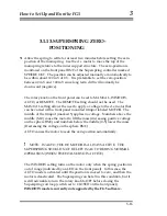
59. Make sure the laser is locked. Set the dropper to OSC mode and press
RESET, then INIT. This moves the cart slowly up and down at a constant
velocity and produces a constant frequency fringe signal which is useful
for adjusting mirror #6.
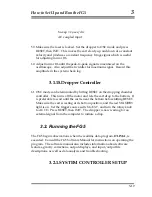
60. Adjust mirror #6 until the peak-to-peak signal is maximized on the
oscilloscope. Also adjust the twiddler for maximum signal. Record this
amplitude in the system check log.
3.1.15.Dropper Controller
61. OSC mode can be terminated by hitting RESET on the dropping chamber
controller. This turns off the motor and lets the cart drop to the bottom. It
is preferable to wait until the cart is near the bottom before hitting RESET.
Make sure the cart is resting at its bottom position, and the red STANDBY
light is on. Set the trigger source switch to EXT, and turn the rotary knob
to AUTO. Press RESET, then INIT. The dropper is now waiting for an
external signal from the computer to initiate a drop.
3.2. Running the FG5
The FG5 begins observations when the realtime data program,
OLIVIA
, is
executed. Consult the FG5 Software Manual for instructions on operating the
program. The software manual also includes information about software
features, gravity corrections, output displays, and input/output file
descriptions, as well as data analysis and trouble shooting.
3.2.1.SYSTEM CONTROLLER SETUP
3-19
Summary of Contents for FG5
Page 22: ...Design Components and Function 2 Figure 2 10 The Superspring 2 14 ...
Page 31: ...Design Components and Function 2 Figure 2 13 Rotation Monitor 2 23 ...
Page 32: ......
Page 42: ...How to Set Up and Run the FG5 3 3 10 ...
Page 44: ...How to Set Up and Run the FG5 3 Figure 3 2 V Post 3 12 ...
Page 53: ...How to Set Up and Run the FG5 3 1 Backup the data 2 Shut off computer power 3 21 ...
Page 87: ...Adjustment and Maintenance 4 4 29 ...
Page 91: ...Adjustment and Maintenance 4 4 33 ...
Page 104: ...Troubleshooting 5 5 2 ...
Page 117: ...Troubleshooting 5 5 15 ...
Page 131: ...Checklists and Logs Appendix D 9 3 ...
Page 140: ...Checklists and Logs Appendix D Table 9 6 Replacing Drive Belt 9 12 ...
Page 145: ...Checklists and Logs Appendix D Table 9 10 Replace Linear Bearings 9 17 ...
Page 149: ...Checklists and Logs Appendix D Table 9 13 Replace Shaft Encoder 9 21 ...

