


How
to
Set
Up
and
Run
the
FG5
3
AND LEVEL AS POSSIBLE. IT IS BEST TO SET UP THE FG5 ON A
CONCRETE OR HARD TILE FLOOR!
3.1.2.ELECTRONICS CASE
6. Place the electronics case in a convenient location within two meters of the
interferometer. It is helpful (if the site permits) to place the rack adjacent
to the connector end of the laser head with the front side of the rack facing
in the same direction as the beam blocker controls on the interferometer.
Place the computer/system controller on top of the electronics case.
7. Remove the front and rear covers of the electronics case. Remove the
cables from the pouch on the inside of the rear cover.
8. Check the input voltage settings and make sure they are set to the proper
AC line voltage. If the instrument is not set to the correct voltage see
appendix A for instructions on how to change the voltage selection..
9. Make sure the following switches are
off
:
•
Main AC power (rear)
•
Main DC power (rear)
•
Laser power (main AC power and key switch)
•
Universal Time Interval Counter
•
Superspring coil
•
Portable ion pump power supply (AC, BAT, and HV)
10. Connect the main AC power cable from the mains power input (rear of
electronics case) to the AC power receptacle.
11. Remove the laser control cable (#7) and laser HV cable (#6) from the
electronics case and connect them to the laser head.
12. Turn on the main AC and DC power switches on (rear of electronics case).
13. Turn on power to the laser. Consult the instructions below for the proper
laser.
3-2
Summary of Contents for FG5
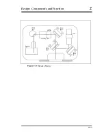
Page 22: ...Design Components and Function 2 Figure 2 10 The Superspring 2 14 ...
Page 31: ...Design Components and Function 2 Figure 2 13 Rotation Monitor 2 23 ...
Page 32: ......
Page 42: ...How to Set Up and Run the FG5 3 3 10 ...
Page 44: ...How to Set Up and Run the FG5 3 Figure 3 2 V Post 3 12 ...
Page 53: ...How to Set Up and Run the FG5 3 1 Backup the data 2 Shut off computer power 3 21 ...
Page 87: ...Adjustment and Maintenance 4 4 29 ...
Page 91: ...Adjustment and Maintenance 4 4 33 ...
Page 104: ...Troubleshooting 5 5 2 ...
Page 117: ...Troubleshooting 5 5 15 ...
Page 131: ...Checklists and Logs Appendix D 9 3 ...
Page 140: ...Checklists and Logs Appendix D Table 9 6 Replacing Drive Belt 9 12 ...
Page 145: ...Checklists and Logs Appendix D Table 9 10 Replace Linear Bearings 9 17 ...
Page 149: ...Checklists and Logs Appendix D Table 9 13 Replace Shaft Encoder 9 21 ...