


Design: Components and Function
2
2.5.2.DROPPER CONTROLLER
The dropper controller
uses
three modes to operate the dropping chamber.
These modes are OSC, AUTO, and MANUAL. The operator also controls the
status of these modes and the dropper triggering with the RESET and INIT
switches and the trigger source (INT/EXT) switch. See Chapter 4 for a
detailed discussion of the modes and switches.
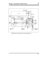
The dropper controller can direct the motor in the Dropping Chamber to lift
the cart and test mass to a specified height, to move the cart at a specified
velocity, and to track the test mass during free-fall.
The motor drives the cart/test mass assembly by turning a pulley and
stainless steel drive belt which is attached to the cart. The motor also turns an
optical shaft encoder that provides accurate information to the dropper
controller on the position and velocity of the pulley.
Information on the relative position of the test mass to the cart during free-fall
is provided by a sphere detector system. An LED and a linear detector are
mounted on opposite sides of the cart, and an optical glass sphere is mounted
on the test mass. The sphere focuses a beam of light from the LED onto the
linear detector, indicating the precise location of the center of the sphere
relative to the cart. The dropper controller uses this information to determine
whether to maintain, increase, or decrease current to the motor to achieve the
appropriate relative position of the cart and the test mass. This feedback
system is a conventional analog servo system.
2.5.3.SUPERSPRING CONTROLLER
2-19
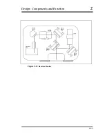
The purpose of the electronic and mechanical systems for the Superspring is
to isolate the reference mass from any vertical motion of the instrument in
order to keep the path length of the test beam constant. Three systems
provide coarse and fine adjustment of the spring support structure: a motor
attached to the top of the mainspring, a
linear actuator
coil and magnet
system, and an
aneroid wafer assembly
. A controller circuit board drives the
Summary of Contents for FG5
Page 22: ...Design Components and Function 2 Figure 2 10 The Superspring 2 14 ...
Page 31: ...Design Components and Function 2 Figure 2 13 Rotation Monitor 2 23 ...
Page 32: ......
Page 42: ...How to Set Up and Run the FG5 3 3 10 ...
Page 44: ...How to Set Up and Run the FG5 3 Figure 3 2 V Post 3 12 ...
Page 53: ...How to Set Up and Run the FG5 3 1 Backup the data 2 Shut off computer power 3 21 ...
Page 87: ...Adjustment and Maintenance 4 4 29 ...
Page 91: ...Adjustment and Maintenance 4 4 33 ...
Page 104: ...Troubleshooting 5 5 2 ...
Page 117: ...Troubleshooting 5 5 15 ...
Page 131: ...Checklists and Logs Appendix D 9 3 ...
Page 140: ...Checklists and Logs Appendix D Table 9 6 Replacing Drive Belt 9 12 ...
Page 145: ...Checklists and Logs Appendix D Table 9 10 Replace Linear Bearings 9 17 ...
Page 149: ...Checklists and Logs Appendix D Table 9 13 Replace Shaft Encoder 9 21 ...


