


Design: Components and Function
2
2.3. The
Superspring
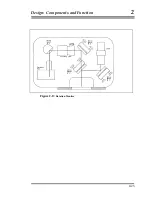
The Superspring (Figure 2-10) is a long-period, active vertical isolator used to
compensate for small vertical motions of the first beam splitter. The
Superspring has a short (20-cm) mainspring with a natural period of about 1
second. The mainspring is contained in a support housing that is actively
servo-controlled to track the Superspring mass at the end of the mainspring.
The resulting system is a long-period (30-60 second) spring-mass system
which is suspended from the interferometer base. The Superspring isolated
ground motions occurring at a higher frequency than its own enhanced
natural frequency.
2.3.1.SUPERSPRING MASS
The Superspring mass contains a
corner cube
retroreflector and an optical
glass sphere
.
2.3.2.SPHERE DETECTOR SYSTEM
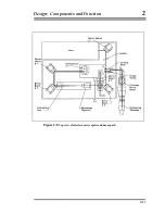
The Superspring sphere detector system (Figure 2-11) senses motions of the
Superspring mass relative to the support housing. An infrared light emitting
diode (LED) located on the support housing directs light through an optical
glass sphere attached to the Superspring mass. The sphere focuses the light
onto a split photodiode detector, also mounted on the support housing. The
support housing is itself servo-driven to cancel these motions using an
electromagnetic coil-type linear actuator (coil) is mounted between the
support housing and the Superspring base. As vertical ground motion occurs
the linear actuator moves the support housing up or down as needed. The
apparatus is constrained to move only vertically by a linear way system
constructed of five flexures (delta rods) arranged in an upper V-shaped array,
and a lower triangular array.
2-13
Summary of Contents for FG5
Page 22: ...Design Components and Function 2 Figure 2 10 The Superspring 2 14 ...
Page 31: ...Design Components and Function 2 Figure 2 13 Rotation Monitor 2 23 ...
Page 32: ......
Page 42: ...How to Set Up and Run the FG5 3 3 10 ...
Page 44: ...How to Set Up and Run the FG5 3 Figure 3 2 V Post 3 12 ...
Page 53: ...How to Set Up and Run the FG5 3 1 Backup the data 2 Shut off computer power 3 21 ...
Page 87: ...Adjustment and Maintenance 4 4 29 ...
Page 91: ...Adjustment and Maintenance 4 4 33 ...
Page 104: ...Troubleshooting 5 5 2 ...
Page 117: ...Troubleshooting 5 5 15 ...
Page 131: ...Checklists and Logs Appendix D 9 3 ...
Page 140: ...Checklists and Logs Appendix D Table 9 6 Replacing Drive Belt 9 12 ...
Page 145: ...Checklists and Logs Appendix D Table 9 10 Replace Linear Bearings 9 17 ...
Page 149: ...Checklists and Logs Appendix D Table 9 13 Replace Shaft Encoder 9 21 ...


