Page 35
Assembly
optoNCDT 1900 / EtherCAT
5.4.5
Turning on the Laser
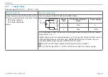
The measuring laser on the sensor is switched on via a software command or a switching input. This allows to switch off the sensor
for maintenance purposes or similar. Response time: after the laser is switched on, the sensor needs approx. 10 ms to send correct
measured data.
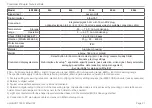
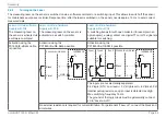
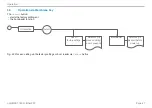
Laser on/off via software,
Supply with PoE
The measuring laser on
the sensor is activated via
a software command.
Laser on/off via hardware,
Supply with PoE
The measuring laser on the sensor is
activated via a switch or similar.
Laser on/off via hardware,
Supply without PoE
A switching transistor with open collector (for example in an
optocoupler), a relay contact or a digital TTL or HTL signal are
suitable for switching.
Activation using the
PC1900-IE-x/RJ45 cable
is possible.
Activation using the
PC1900-IE-x/OE-RJ45 possible.
Activation using the
PC1900-IE-x/OE-RJ45 possible.
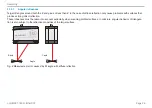
PC1900-IE-x/OE-RJ45
7
Violet
8
ILD1900-IE
Black
GND
V
H
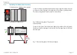
PC1900-IE-x/OE-RJ45
7
1
Violet
8
Type 1
ILD1900-IE
Type 2
Type 3
Black
V
+
10k
V
H
The inputs are not electrically separated.
24 V logic (HTL): Low level ≤ 3 V; High level ≥ 8 V (max 30 V)
internal pull-up resistor, an open input is detected as High.
Max. switching frequency 10 Hz.
The ground of the logic circuit must be galvanically connect-
ed to "Laser on/off -".
No external resistance is required for current limitation. For permanent "Laser on", connect the black and
violet wires.
Summary of Contents for ILD1900-10
Page 8: ...optoNCDT 1900 EtherCAT ...
Page 110: ...Page 110 Appendix EtherCAT Documentation optoNCDT 1900 EtherCAT ...
Page 111: ......

