


64Z1103C
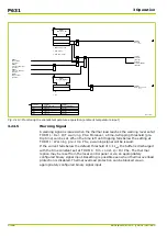
CBF_1:
Current flow A
[ 038 230 ]
I
̲
A
I
̲
B
I
̲
C
CBF_1:
Current flow B
[ 038 231 ]
CBF_1:
Current flow C
[ 038 232 ]
CBF_1:
Current flow Phx
[ 038 233 ]
CBF_1:
IN<
[ 022 180 ]
CBF_1:
Evaluation IN
[ 022 184 ]
0
1
2
0: Without
2
I
̲
N
1 ... 2
CBF_1:
Current flow N
[ 038 235 ]
CBF:
IN
460 394
1
1: Calculated
2: Measured
≥
1
c1
c2
CBF_1:
I<
[ 022 160 ]
+
+
+
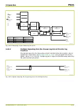
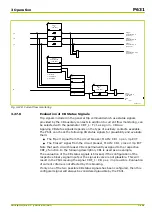
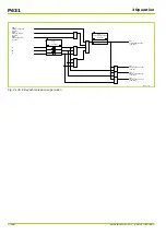
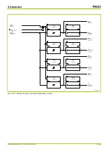
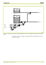
Fig. 3-128: Current flow monitoring
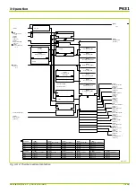
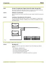
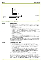
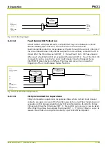
3.27.8
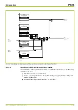
Evaluation of CB Status Signals
Trip signals included in the general trip command which use status signals
provided by the CB auxiliary contacts in addition to current flow monitoring, can
be selected with the parameter CBF_1: Fct.assignm. CBAux. .
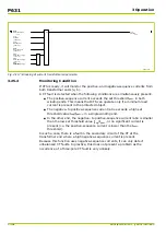
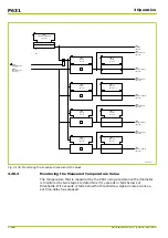
Applying CB status signals depends on the type of auxiliary contacts available.
The P631 can check the following CB status signals for plausibility and evaluate
them:
●
The ‘Open’ signal from the circuit breaker, MAIN: CB1 open 3p EXT
●
The ‘Closed’ signal from the circuit breaker, MAIN: CB1 closed 3p EXT
Note that each circuit breaker CBx is permanently assigned to the respective
CBF_x function. In the following description, CB1 is used as an example.
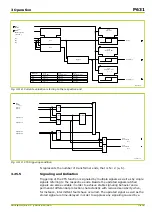
The evaluation of the CB status signals is blocked, if the configuration of the
respective binary signal inputs or the signal levels are not plausible. This will
result in the P631 issuing the signal CBF_1: CB pos. implausible. Evaluation
of current criteria is not affected by this blocking.
If only one of the two possible CB status signals has been configured, then this
configured signal will always be considered plausible by the P631.
3 Operation
P631
P631/EN M/R-11-C // P631-310-650
3-161
Summary of Contents for P631
Page 2: ......
Page 4: ......
Page 7: ...Changes after going to press...
Page 8: ......
Page 16: ...P631 Table of Contents 8 P631 EN M R 11 C P631 310 650...
Page 56: ...P631 2 Technical Data 2 28 P631 EN M R 11 C P631 310 650...
Page 236: ...P631 3 Operation 3 180 P631 EN M R 11 C P631 310 650...
Page 246: ...P631 4 Design 4 10 P631 EN M R 11 C P631 310 650...
Page 266: ...P631 5 Installation and Connection 5 20 P631 EN M R 11 C P631 310 650...
Page 276: ...6 8 Configurable Function Keys P631 6 Local Control HMI 6 10 P631 EN M R 11 C P631 310 650...
Page 548: ...P631 10 Commissioning 10 10 P631 EN M R 11 C P631 310 650...
Page 568: ...P631 12 Maintenance 12 8 P631 EN M R 11 C P631 310 650...
Page 570: ...P631 13 Storage 13 2 P631 EN M R 11 C P631 310 650...
Page 572: ...P631 14 Accessories and Spare Parts 14 2 P631 EN M R 11 C P631 310 650...
Page 576: ...P631 15 Order Information 15 4 P631 EN M R 11 C P631 310 650...
Page 582: ...P631 A2 Internal Signals A2 4 P631 EN M R 11 C P631 310 650...
Page 608: ...P631 A4 Telecontrol Interfaces A4 18 P631 EN M R 11 C P631 310 650...
Page 637: ......