MicaSense RedEdge-MX™ and DLS 2
Integration Guide
Revision 04
November 2020
Seattle, WA
© 2020 MicaSense, Inc
MSPN 900-00022
Page 1: ...MicaSense RedEdge MX and DLS 2 Integration Guide Revision 04 November 2020 Seattle WA 2020 MicaSense Inc MSPN 900 00022...
Page 2: ...ation 8 Configuration Options 9 Default Overlap mode 9 Default trigger by HTTP API 10 MAVLink with PixHawk or similar flight controller 11 DLS 2 with Aircraft GPS 11 HTTP Connection 12 Serial Connecti...
Page 3: ...customized integrations Advanced integrations take advantage of flexible interfaces including Ethernet serial and PWM GPIO trigger for seamless integration with any aircraft Firmware It is important...
Page 4: ...w 47 2 degrees horizontal 35 4 degrees vertical Output bit depth 12 bit GSD 120 m 400 ft 8 cm pixel per band GSD 60 m 200 ft 4 cm pixel per band Center wavelengths and bandwidth Cameras with serial nu...
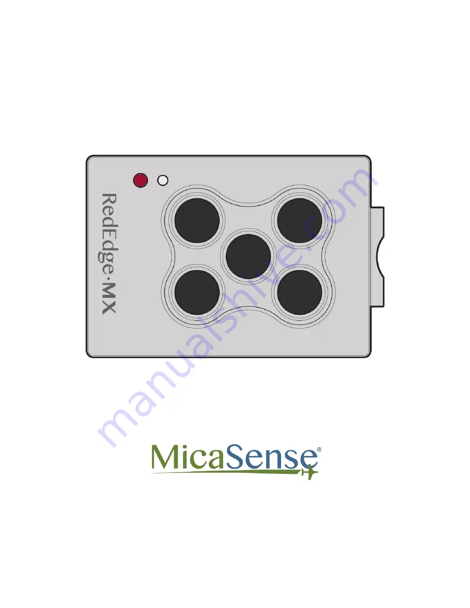
Page 5: ...ber and output 1 Blue 2 Green 3 Red 4 NIR 5 Red edge Measurements and Attachment Points There are four M3 screw holes at 60 mm x 35 mm on center The sensor can be attached to the host aircraft using a...
Page 6: ...November 2020 Page 5 of 21 2020 MicaSense Inc...
Page 7: ...November 2020 Page 6 of 21 2020 MicaSense Inc...
Page 8: ...aircraft Make sure the sensor points straight down with respect to the earth at all times during flight The best way to ensure this is to use a gimbal Normally the sensor should be in landscape orient...
Page 9: ...guide Connect a compatible power supply to the camera s power pins For more details about power see the Input and Output section of this guide Once attached to the aircraft use the Flight Calculator t...
Page 10: ...Link v1 0 messaging protocol for the serial API which the camera uses to interact with PixHawk You can read more detailed information here Guide for MicaSense Sensors and PixHawk DLS 2 with Aircraft G...
Page 11: ...ection of this document for pin layout and details Visit https www micasense com api to learn more about communicating with the MAVLink API Input and Output The RedEdge MX DLS 2 sensor kit includes al...
Page 12: ...own Power Input Item Value Nominal Voltage 5 0 V DC Input Voltage Range 4 0V 15 8V DC Average Power 3 5 Watts average 8 0 W peak Camera Not Providing Power to External GPS Module 4 0 Watts average 8 5...
Page 13: ...ising edge pulse falling edge pulse or a PWM signal such as is typically used with standard servos When using a PWM signal as the trigger the camera detects a transition from a long PWM to a short PWM...
Page 14: ...ndard TTL level serial port as well as an Ethernet port Documentation for the communications protocol is available by contacting MicaSense Pin Signal Direction 1 Serial RX 3 3 V Output From Camera 2 S...
Page 15: ...timal efficiency Ensure the power source conforms to the specifications listed above and can supply the required voltage at the power port of the camera accounting for any losses in the wiring USB por...
Page 16: ...es the forward overlap and cannot account for the side overlap which must be calculated in a flight planner using the sensor s field of view to create an appropriate row spacing We recommend this mode...
Page 17: ...ssing the sensor via its Wi Fi access point the sensor IP address will be 192 168 10 254 When the sensor is connected to an Ethernet network the sensor IP address will be 192 168 1 83 by default The s...
Page 18: ...rectly to RedEdge MX During a mission the DLS 2 measures the ambient light and sun angle and records this information in the metadata of the TIFF images captured by the camera This information can the...
Page 19: ...November 2020 Page 18 of 21 Measurements and Attachment Points Height 14 03 mm Width 46 00 mm Length 63 50 mm Weight 49 g 2020 MicaSense Inc...
Page 20: ...The signal types are outlined in the User Guide for MicaSense Sensors The camera trigger button will command a capture on the RedEdge MX This is useful for capturing a preflight image of the calibrati...
Page 21: ...connector on the DLS 2 should be facing forward in the flight direction Mounting it in the opposite direction will cause the magnetometer calibration process to be backwards but will otherwise still...
Page 22: ...nd DLS 2 Integration Guide Revision 04 November 2020 MSPN 900 00022 MicaSense Inc Seattle WA 98103 The contents of this guide are subject to change without notice MicaSense Inc assumes no liability fo...
Page 23: ...November 2020 Page 22 of 21 Revision History Revision Description Date 03 Previous version April 2019 04 Updated the match Altum guide November 2020 2020 MicaSense Inc...