MicaSense Altum™ and DLS 2
Integration Guide
Revision 10
June 2020
Seattle, WA
© 2020 MicaSense, Inc
MSPN 900-00021-01
Page 1: ...MicaSense Altum and DLS 2 Integration Guide Revision 10 June 2020 Seattle WA 2020 MicaSense Inc MSPN 900 00021 01 ...
Page 2: ...ion 7 Configuration Options 8 Default Overlap mode 8 Default trigger by HTTP API 9 MAVLink with PixHawk or similar flight controller 9 DLS 2 with Aircraft GPS 10 HTTP Connection 10 Serial Connection 10 Input and Output 11 Host Interface Connector Power and Data I O 12 Power supply specifications 12 Input and Output 13 USB Storage and Ethernet 13 Capture Rate 14 Accessory Port ACC 14 Automatic Capt...
Page 3: ...power to the sensor to fully customized integrations Advanced integrations take advantage of flexible interfaces including Ethernet serial and PWM GPIO trigger for seamless integration with any aircraft Firmware It is important to have the latest version of firmware installed on your sensor Please see the following page to get the latest version and learn how to update your firmware https www mica...
Page 4: ...agers 160 x 120 px 0 01 K Aspect ratio 4 3 4 3 Sensor size 7 12 x 5 33 mm 8 9 mm diagonal 1 92 x 1 44 mm Focal length 8 mm 1 77 mm Field of view h x v 48º x 36 8º 57º x 44 3º Thermal sensitivity n a 50 mK Thermal accuracy n a 5 K Output bit depth 12 bit 14 bit GSD 120 m 400 ft 5 2 cm 81 cm GSD 60 m 200 ft 2 1 cm 41 cm 2020 MicaSense Inc ...
Page 5: ... wavelengths and bandwidth Cameras with serial number AL05 or higher Name Center Bandwidth Blue 475 nm 32 nm Green 560 nm 27 nm Red 668 nm 16 nm Red edge 717 nm 12 nm Near infrared 842 nm 57 nm Thermal 11 μm 6 μm 2020 MicaSense Inc ...
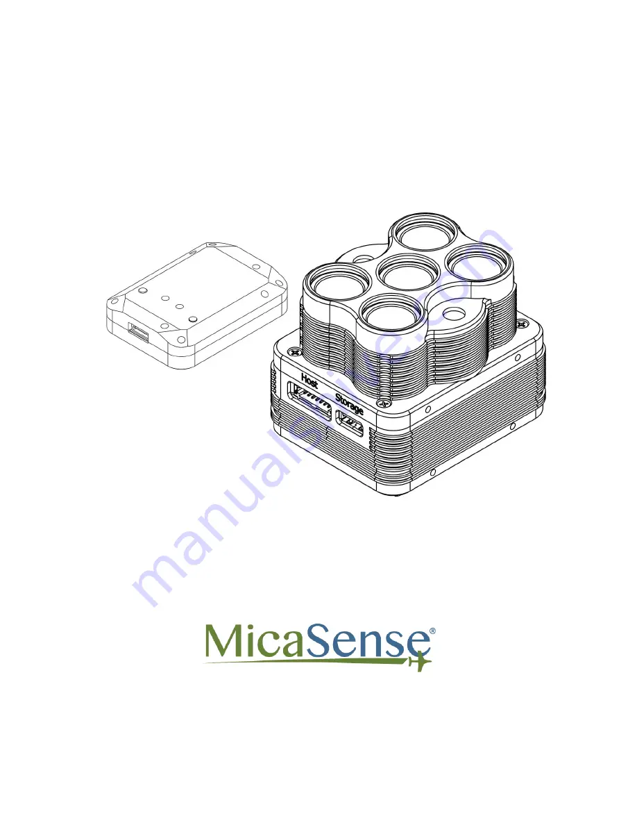
Page 6: ...band number and output 1 Blue 2 Green 3 Red 4 NIR 5 Red edge 6 Thermal Measurements and Attachment Points There are four M3 screw holes at 60 mm x 35 mm on center The sensor can be attached to the host aircraft using at least two of the four provided threaded mounting points and M3 x 0 5 screws If using only two mounting points it is important to choose two threaded points opposite of each other 2...
Page 7: ...June 2020 Page 6 of 21 Length 82 mm Width 67 mm Height 64 5 mm Weight 357 g 2020 MicaSense Inc ...
Page 8: ...raft Make sure the sensor points straight down with respect to the earth at all times during flight The best way to ensure this is to use a gimbal Airflow over all surfaces of the sensor is necessary for proper heat dissipation Do not run Altum on the bench or in the field for extended periods of time without airflow Do not completely cover or insulate the back surface of the sensor Normally the s...
Page 9: ...is guide Connect a compatible power supply to pins 1 and 2 on the HOST connector For more details about power see the Input and Output section of this guide Once attached to the aircraft use the Flight Calculator to determine the necessary overlap percentage for your desired Ground Sample Distance and Target Altitude then input the parameters into the Overlap settings outlined in the Triggering se...
Page 10: ...omputer See examples of the HTTP API here Integration examples for MicaSense sensors MAVLink with PixHawk or similar flight controller The Altum can be triggered with a PixHawk flight control system using the serial API MicaSense cameras currently use the MAVLink v1 0 messaging protocol for the serial API which the camera uses to interact with PixHawk You can read more detailed information here Gu...
Page 11: ...mage metadata overriding the DLS 2 internal GPS data for five seconds or until another update is sent via the API HTTP Connection Attach a USB Ethernet adapter or USB Wi Fi adapter to one of the USB 3 ports See the User Guide for MicaSense Sensors for connection details and information For HTTP API details visit https www micasense com api Serial Connection Use the provided pigtail from the host c...
Page 12: ... Output The Altum DLS 2 sensor kit includes all necessary cables for integration If extending the cables ensure that the voltage at the camera is at acceptable levels as outlined in the Powering section of this guide 2020 MicaSense Inc ...
Page 13: ...nse Samtec 14pin 2 00mm Tiger Eye PN T2M 107 01 S D RA WT 13 DLS RX CAM TXF 11 DLS AUX OUT CAM INF 9 DLS POWER 7 CAM HOST PPS IN 5 CAM RX HOST TX 3 CAM PPS OUT 1 POWER 14 DLS TX CAM RXF 12 DLS PPS OUT CAM PPS IN 10 DLS GND 8 ISO GND 6 TRIG IN 4 CAM TX HOST RX 2 GND Power supply specifications Voltage 5 2 V 25 2 V Standby 5 5 W Average 7 W Peak 10 W 2020 MicaSense Inc ...
Page 14: ... PWM Trigger Expected Range 1 0 ms to 2 0 ms VIH High level input voltage 2 0 V to 5 5 V VIL Low level input voltage 0 0 V to 0 8 V All 3 3V HOST IO lines are referenced to ISO GND Pin 8 To ensure proper operation of Trigger Serial and PPS lines make sure ISO GND is connected to your host system s IO ground This ground is isolated from the Altum power supply ground and must be connected for the IO...
Page 15: ... Capture Triggering Altum supports three methods for capturing images Overlap Timer and External Trigger To learn more about how to configure these settings please see the User Guide for MicaSense Sensors Overlap recommended In Overlap mode when the aircraft climbs to within your chosen Target Altitude Tolerance below your Target Altitude Altum will start capturing and only take a capture if it ha...
Page 16: ... used with standard servos When using a PWM signal as the trigger the sensor detects a transition from a long PWM to a short PWM or vice versa When using PWM rising edge or falling edge ensure that the input signal s ground is connected to the isolated ground pin 8 on the Altum HTTP API Ethernet and Wi Fi The HTTP API is the most powerful way to interface with the Altum You can use this API using ...
Page 17: ...trigger commands directly from the drone via PSDK HTTP or MAVLink depending on the integration Thermal Non Uniform Calibration NUC Performing Non Uniform Calibrations on NUCing thermal images helps reduce image noise resulting in better thermal image quality The auto NUCing feature is enabled on boot and ensures that the calibration is up to date with NUCs occuring every five minutes or when the t...
Page 18: ...he TIFF images captured by the camera This information can then be used by specialized processing tools like Pix4Dmapper to correct for global lighting changes in the middle of a flight such as those that can happen due to clouds covering the sun In addition the DLS 2 provides GPS data to Altum unless GPS data is provided from an external source as outlined earlier in this guide If using an altern...
Page 19: ...21 Measurements and Attachment Points Height 14 03 mm Width 46 00 mm Length 63 50 mm Weight 49 g DLS 2 Connectors and Buttons The sensor kit includes all required interface cables to connect to the DLS 2 2020 MicaSense Inc ...
Page 20: ...Sense Sensors The camera trigger button will command a capture on the Altum This is useful for capturing a preflight image of the calibration panel but care should be taken not to cover or shade any of the light sensors when pressing the button Older DLS 2 have an RF connector This connector is not used by the DLS 2 or camera 2020 MicaSense Inc ...
Page 21: ...nector on the DLS 2 should be facing forward in the flight direction Mounting it in the opposite direction will cause the magnetometer calibration process to be backwards but will otherwise still work Fixed wing Always install the DLS 2 at the high point of the fuselage if possible to avoid any shadowing or reflections from the aircraft fuselage tail or propellers Do not recess or embed the DLS 2 ...
Page 22: ... 2 Integration Guide Revision 10 June 2020 MSPN 900 00021 01 MicaSense Inc Seattle WA 98103 The contents of this guide are subject to change without notice MicaSense Inc assumes no liability for incidental or consequential damages arising from the use of this product and any claims by a third party Copying of the contents of this guide in whole or in part is prohibited under the copyright law 2020...
Page 23: ...tion Date 08 Initial Release 26 Apr 2019 09 Added inputs and outputs 18 Jun 2019 10 Updated band wavelengths added NUC info updated What s included clarified USB Ethernet options noted the need to be on latest firmware version 02 June 2020 2020 MicaSense Inc ...