


Instruction Manual MIC type EC-912
Revision no.4
23 / 38
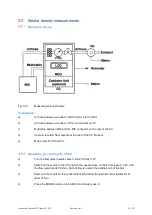
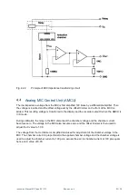
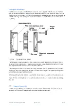
Fig. 4.2.2
Principle of MIC impedance transforming circuit
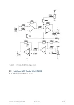
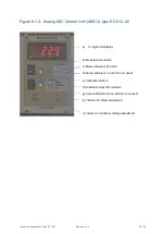
Analog MIC Control Unit (AMCU)
The low impedance voltage from the MIC is first amplified 100 times by a differential amplifier. Then
the voltage is inverted and the offset voltage set by the offset trimmer on the front of the MCU is
added. This resulting voltage is transferred to the display and the recorder output X when the AMCU is
in X mode.
During calibration the relay in the MIC disconnect the chamber voltage and the chamber current
becomes zero. The voltage to the MCU also becomes zero and the offset trimmer is then used to
adjust the X value to 1.00.
The voltage from the Uc trimmer is amplified and used for adjustment of the chamber voltage in the
MIC. The chamber current is proportional to the applied chamber voltage and the chamber voltage is
used to adjust the chamber current to 100 pA in aerosol free air. A chamber current of 100 pA equals
hence an X value of 0.00.