


Instruction Manual MIC type EC-912
Revision no.4
22 / 38
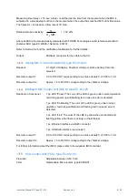
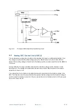
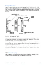
Fig. 4.2.1
Principle of ionization chamber design in the MIC
The radioactive source is mounted in a holder which may be unscrewed for cleaning purposes, refer to
Section 5.1.1.
The chamber is operated in the proportionality range with a clean air quiescent current of 10
-
10
A (100
pA) corresponding to a chamber voltage of approx. 19 V.
Electronics for impedance transformation
An impedance transforming circuit is built into the MIC. The principle of the impedance transforming
circuit is shown in Fig. 4.2.2
.
The circuit converts the ionization current at a high impedance level to a
proportional voltage at a low impedance level. So, the length of the connecting cable between the MIC
and the CC becomes uncritical.
The relay, which is shown in Fig. 4.2.2
,
is used for calibration of the impedance transforming circuit
and the MCU. This facility will be described in Section 4.4.