


Instruction Manual MIC type EC-912
Revision no.4
17 / 38
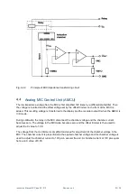
Offset trimmer:
Screwdriver trimmer for offset calibration.
U
c
trimmer:
Screwdriver trimmer for adjustment of the chamber CAL voltage.
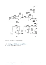
Intelligent MIC Control Unit (IMCU)
Front panel (see Fig. A.1.5 in Annex 1). See also the separate IMCU user manual.
Flow Control Unit (FCU)
Front panel (see Fig. A.1.3 in Annex 1)
Flow meter valve:
Needle valve for adjustment of air flow rate in the range 0-50 l/min. The flow
rate is indicated on the flow meter and read at the middle of the ball.
Rear panel (see Fig. A.1.4 in Annex 1)
Air inlet:
Pipe branch for hose to air outlet on MIC.
Air outlet:
Pipe branch for hose to air inlet on VP.
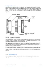
Finger screws:
Screws for disassembling the filter unit.
Vacuum Pump (VP)
Air inlet:
Pipe branch for hose to air outlet on rear of FCU.
Air outlet:
Pipe branch for hose to appropriate place.
Bypass valve:
Valve for adjustment of minimum pressure. The bypass valve is fitted to
ensure that the pressure does not drop below 150 mbar, when the inlet is
blocked. Before delivery of a new vacuum pump from FORCE Technology,
the bypass valve is adjusted to a minimum pressure of approx. 500 mbar. This
setting is locked with lacquer and should not be changed.