511 Series Programmable Attenuator
VERSION 2
User Guide
Page 1: ...511 Series Programmable Attenuator VERSION 2 User Guide ...
Page 2: ...2 ...
Page 3: ...3 Table of Contents Specifications 3 Initial Setup 4 Local Mode Operation 4 Front and Back Panel View 5 Implementing Custom GPIB Connection 6 Implementing Custom USB Connection 8 Index 9 ...
Page 4: ...4 Specifications Supply Voltage 24V Attenuator Speed 35 dB s Max Attenuation 70 dB Resolution 0 01 dB USB Port Type 2 0 GPIB Protocol National Instruments 488 2 ...
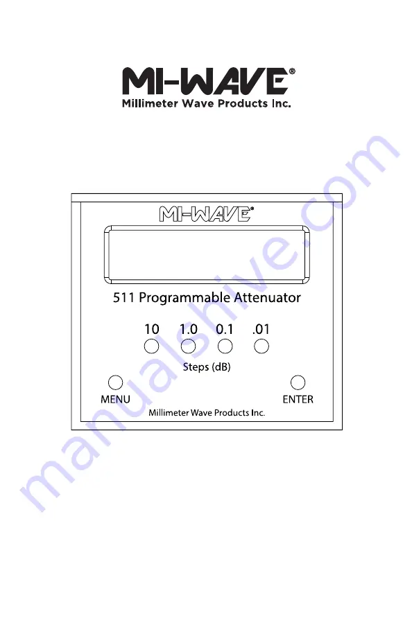
Page 5: ...ressing 10 and 1 0 until the correct values are listed Press ENTER to save GPIB Address To set the GPIB address press 01 to select the desired address in range 1 30 and then press MENU to store the address and exit Once the address is set and stored ON OFF Power cycling will not change the address Local Mode The unit can switch to Local Mode by pressing MENU followed by 10 and a second MENU press ...
Page 6: ...6 Front and Back Panel View ON OFF Figure 1 Front Panel View Figure 2 Back Panel View ...
Page 7: ...lick the DEVICES AND INTERFACE tab Device will be listed as NI GPIB USB HS GPIBx where x is the board index 3 Enter the primary GPIB address of the unit To change the primary GPIB address refer to section 1 5 4 Secondary address is never used and must always be set to 0 5 For timeout enter 13 6 Enter 1 for EOI on last byte flag 7 Enter 0 for end of string mode byte 8 The unit will then exit the sc...
Page 8: ...board index entered in the command This should be called before closing any custom GPIB communication programs with the device A demonstration is shown below in Figure 6 for board index 0 Figure 5 Screenshot of command ibrd to read response from GPIB Figure 6 Screenshot of command ibonl for board index 0 Warning Never leave unconnected GPIB cables attached to the device during use this can distort...
Page 9: ...ty 1 stop bit No Flow Control Any method of creating a serial port connection with these settings will suffice One simple solution is to use the C NET SerialPort class to create custom USB communication software for the device Send attenuation commands ranging from 0 to 70 terminated via r n CRLF If each command is not terminated by r n the serial buffer on the device will continue to fill up with...
Page 10: ...Clock 5 F Frequency Band 5 Front Panel 6 G GPIB 7 8 I ibdev 7 8 ibonl 8 ibrd 8 ibwrt 8 L Local Mode 5 M Manufacturing Date 5 N NI MAX 7 R Remote Mode 5 S Serial Number 5 Serial Port 9 U USB 9 V Virtual COM Port VCP 9 Index ...
Page 11: ...11 ...
Page 12: ...Millimeter Wave Products Inc 2007 Gandy Blvd Suite 1310 Saint Petersburg FL 33702 Phone 727 563 0034 Fax 727 563 0031 Email sales miwv com www miwv com ...