EN
Control CS 320 / Rev.B 1.01 – 1
Operating Instructions
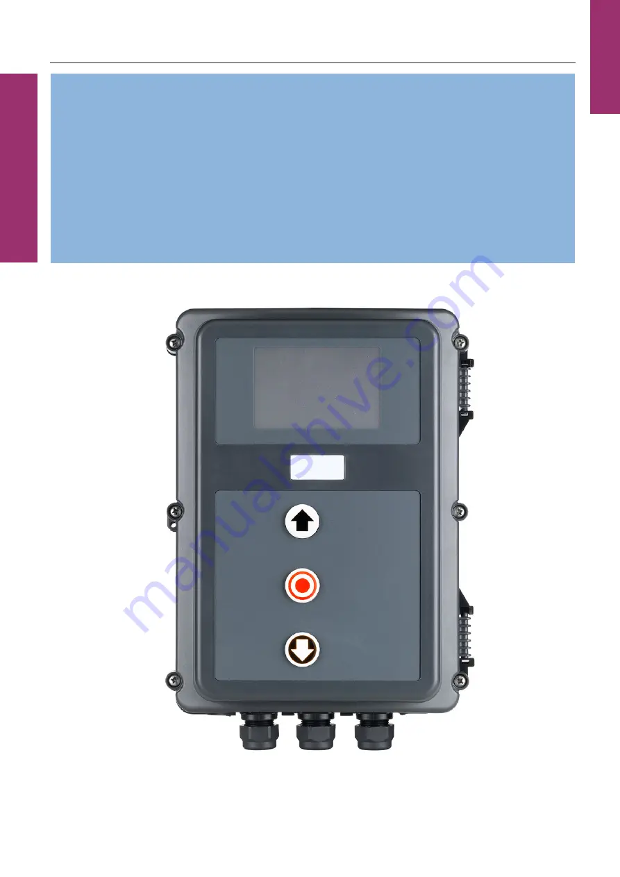
Control CS 320
Page 1: ...EN Control CS 320 Rev B 1 01 1 Operating Instructions Control CS 320...
Page 2: ...stem radio 25 6 Initialisation 25 7 Setting the limit positions 26 7 1 Checking the drive travel direction 26 7 2 Setting the mechanical limit switches 26 7 3 Setting the electronic end position syste...
Page 3: ...ctricians may connect programme and service the control Qualified and trained electricians must meet the following requirements Knowledge of the general and specific safety and accident prevention reg...
Page 4: ...sible to connect drives with mechanical limit switches MEC or an electronic limit position system AWG All the necessary command devices and safety elements can be connected set and evaluated Programmi...
Page 5: ...BUS system MS BUS X18 Connector strip for frequency converter interface X19 Terminal strip for supplying external devices 230V 50Hz X20 Connector strip for transmission system X21 Mains voltage selec...
Page 6: ...is fitted and ready for operation The command and safety devices are fitted and ready for operation The control housing with the CS 320 controller is fitted Observe the valid standards and regulation...
Page 7: ...mechanical limit switch MEC to the controller Connect controller to the motor Connect controller to the motor Connect controller to the mains network Connect controller to the mains network Secure ca...
Page 8: ...0 Hz N PE F2 1 F2 2 F2 3 5 4 2 PE PE PE N L3 L2 L1 X1 X21 3 400 V 50 Hz N PE F2 3 F2 2 F2 1 PE PE PE N L3 L2 L1 X1 X21 F1 X19 3 230 V 50 Hz PE F2 1 F2 2 F2 3 AUF ZU PE PE PE L N X1 X21 F1 X19 X11 X18...
Page 9: ...y crank or emergency chain NOTE In order to satisfy the requirements of EN 12453 2017 the electronic end position system must comply as a minimum with PL c with a min category 2 per EN ISO 13849 1 In...
Page 10: ...S1 Supplementary limit switch UP S2 Limit switch UP S3 Safety limit switch UP S4 Safety limit switch DOWN S5 Limit switch DOWN S6 Supplementary limit switch DOWN S7 Emergency operation NC contact S8 M...
Page 11: ...improper installation Connection as a 6 wire solution is prohibited and can lead to destruction of the CS 320 circuit board Reference potential on X2 B1 B2 24V DC Reference potential on X15 12V DC 1...
Page 12: ...ht of the door may only be given via input 1 MOD32 X4 9 10 If the command device is not a key switch Install it at a height of at least 1 5 m Install it at a height of at least 1 5 m Install it where...
Page 13: ...keypad is not connected Cover keypad CS Silicone keys with NO contacts From year of manufacture 01 2010 X13 5 8 8 External radio receiver 1 2 3 4 5 6 7 8 9 10 X4 1 2 3 4 5 6 7 8 9 12 11 10 X19 X3 F1 2...
Page 14: ...connection cable A is pluggable 1 2 3 4 5 6 7 8 9 10 A BK BU WH BN X4 GN GY 11 12 5 9 1 Light grid 2 Parameter INPUT 2 MOD 12 The connection cable A is pluggable 1 2 3 4 5 6 7 8 9 10 A BK BU WH BN X4...
Page 15: ...uent change the respective system must be selected via a parameter setting in the INPUT operating mode In the case of light barriers with a test function this must be set manually 10 2 Input operating...
Page 16: ...barrier 4 wire NC without testing parameter LIGHT BARR 1 MOD 3 with testing parameter LIGHT BARR 1 MOD 5 OUT NC 1 2 3 4 5 6 7 8 9 12 11 10 X4 R T 5 11 1 Light barrier MFZ 2 wire with testing paramete...
Page 17: ...put in the INPUT operating mode 5 13 5 13 Connection of programmable inputs Connection of programmable inputs The controller CS 320 has 3 programmable inputs for which different functions can be selec...
Page 18: ...mer pluggable brake monitoring module BWM1 or as connection for monitoring an external load contactor and drive brake Reference potential 5V DC 10 2 Input operating mode Parameter INPUT 3 13 28 26 04...
Page 19: ...ng an external load contactor and the drive brake The parameter INPUT 3 must then be set to MOD22 Connection for monitoring an external load contactor and drive brake optional If the power of the door...
Page 20: ...urs in one of the components the system can no longer be operated and the message ERROR STOP appears on the display 1 4 components on a 8 2 kOhm basis can be linked according to the following wiring d...
Page 21: ...quirements of EN 12453 2017 Alternatively the fall protection can also be equipped with an NC contact and integrated in the safety circuit of the controller X3 1 2 This switch with NC contact must be...
Page 22: ...orage spaces have been deleted have been deleted You can cancel the deletion process by briefly pressing the programming button 5 17 5 17 Digital 991 Digital 991 Connection Plug the radio receiver int...
Page 23: ...cumentation for the BUS modules 5 19 5 19 Connection of frequency converter Connection of frequency converter It is possible to connect a Siemens frequency converter for speed independent control of t...
Page 24: ...n the circuit board for connecting different components The MS BUS LCD monitor 121246 is supplied with a 3 m long connection cable The MS Bus LCD monitor like the standard LCD monitor permits full acc...
Page 25: ...evice Light barrier system Input 2 safety input During this process approx 60 seconds the green LED flashes and the display shows PLEASE WAIT in the top line Operation of the system is not possible at...
Page 26: ...Setting the electronic end position system using the setting buttons on the system using the setting buttons on the circuit board circuit board Change to adjustment mode Press the button P for approx...
Page 27: ...time is learned automatically The display shows TEACH IN RUN The controller functions are the same as in automatic mode 7 5 7 5 Setting the intermediate positions of the Setting the intermediate posit...
Page 28: ...ating modes LCD monitor operating modes With the LCD monitor the controller has four operating modes 1 AUTOMATIC 2 ADJUSTMENT 3 INPUT 4 DIAGNOSIS The operating modes ADJUSTMENT INPUT and DIAGNOSIS are...
Page 29: ...possible to call up and set all input menu parameters 10 2 Input operating mode Note The expert mode is automatically exited after approx 7 minutes if no button is pressed Now only the limited selecti...
Page 30: ...ent mode 7 4 Setting the electronic limit position system via the LCD monitor Change to automatic mode Press P button until AUTOMATIC appears Press P button until AUTOMATIC appears 8 6 8 6 RESETTING t...
Page 31: ...EN Control CS 320 Rev B 1 01 31 Control CS 320 Rev B 1 01 31...
Page 32: ...up menu 2 sec Scroll down menu 2 sec Select value P 1 sec Increase value Reduce value Save value P Back to INPUT operating mode and 1 sec FINE UP 0 P 1 sec FINE DOWN 0 INT POS UP A INT POS DOWN A OPE...
Page 33: ...ll up menu 2 sec Scroll down menu 2 sec Back to AUTOMATIC operating mode P Only interrogation possible UPPER SWITCH ON LOWER SWITCH ON UP SWITCH OFF DOWN SWITCH OFF INPUT 1 OFF INPUT 2 SKS OP 2 SAFE 2...
Page 34: ...s switched off an active signal NO is detected at the UP DOWN pulse or programmable input 1 with use of I O BUS modules also inputs 11 14 or 15 18 This always constitutes an impermissible state The ca...
Page 35: ...ion Sect UP in relation to the saved limit position UP Display as a negative value Only visible with electronic limit position system Automatic teach in of the position 7 5 Setting the intermediate po...
Page 36: ...ide 3 forewarning illuminated door running illuminated MOD4 Pulse signal with UP command from inside MOD5 Fault message MOD6 UP limit position MOD7 DOWN limit position MOD8 UP limit position negated M...
Page 37: ...be set manually when using a light grid Without addition of the open time if programmed after interruption of the light grid during the automatic closing Without switch off of the function Automatic...
Page 38: ...P STOP MOD5 Stop reversing Ride along suppression UP door movement only possible if the light barrier is clear MOD6 No action Stop reversing MOD7 No action Stop rev MOD8 No action Stop MOD9 Ride along...
Page 39: ...INPUT 2 Selection of a function that should be assigned to input 2 X4 11 12 OFF NOT active MOD2 Slip door switch STOP with deviation 8 2 k MOD3 Switching strip active in UP direction 8 2 k Stops and...
Page 40: ...ING TIME Monitoring the maximum running time of an UP or DOWN movement During the teach in run the runtime of the door is learned automatically If the deviation is 20 in both directions a runtime erro...
Page 41: ...orce rotational speed will be displayed during opening With the power monitoring active the value must be set to a lower value than the lowest value shown during the door travel The greater the differ...
Page 42: ...al switches Only appears after activation of input level 2 via parameter PIN no 2 OFF 0 99950 OFF INVERTER Activates or deactivates a connected frequency converter By connecting a frequency converter...
Page 43: ...command Only in CLOSE direction B Position messages MOD Description Remarks MOD6 UP limit position The relay closes the contact when the door is in the OPEN limit position MOD7 DOWN limit position Th...
Page 44: ...rake closed circuit current principle applied in OPEN limit position The switching contact of the brake rectifier is controlled via the relay in order to implement a faster braking function As soon as...
Page 45: ...MOD26 Activation of transmission system radio 2 and radio 4 Before every DOWN command the transmission system radio is activated with a pulse The duration of activation must be set on the transmission...
Page 46: ...ing the programmed service interval Only after the service interval is reset or redefined does the relay drop out again 10 2 Input operating mode on page 35 MOD46 ADJUSTMENT operating mode The relay i...
Page 47: ...losing STOP Interruption of the emergency closing for the duration of activation MOD8 Switch BMA 2 emergency opening NO Control function with an active fire alarm system Open Normal function Closed Em...
Page 48: ...s button outside Pressing the button moves or stops the door Function and direction of the movement depend on the IMPULS parameter setting in the input menu 10 2 Input operating mode IMPULS parameter...
Page 49: ...NP with testing Behaves like light grid 1 SKS MOD 4 6 Light grid active in CLOSE direction Stops and reverses with actuation of the light grid Form of reversing reverse rev is accepted MOD8 Safety swi...
Page 50: ...optionally Programmable INPUT 2 X4 11 12 Input dependent on MOD selected at the programmable input INPUT 2 with MOD 5 7 SKS OPEN 2 with MOD 3 4 SAFE 2 with MOD 2 and MOD8 ON Input 2 is active OFF Inp...
Page 51: ...TOP Command button STOP cover keypad ON Button is not actuated OFF Button is actuated ROT FIELD Shows the currently set rolling direction of the drive RIGHT Setting for a right rotating field LEFT Set...
Page 52: ...scription the frequency of occurrence and the information on which cycle the fault arose most recently Only errors that have already occurred appear in the list The following messages can be read from...
Page 53: ...as been exceeded Check the path of the door and running time Re programme the running time if necessary ERROR AWG Signal transmission between absolute value encoder and controller is interrupted or fa...
Page 54: ...sure wave strip was unsuccessful Check DW switch spiral cable and rubber profile Check DW POINT setting The test of the transmission systems RADIO 1 4 failed Check transmission system RADIO Check rela...
Page 55: ...splay via LED LED H1 green motherboard Fault message LED display Remarks Operating voltage missing Off No supply voltage available LED H2 red motherboard Fault message LED display Remarks SAFETY CIRC...
Page 56: ...POWERSEGM 11 x flashing The load contactor or a relay is defective The circuit board must be replaced ERROR STOP Continuous illumination travel no longer possible An error has occurred at the safety...
Page 57: ...erformance Level C for electrical safety strips with 8 2 k terminal resistance and for dynamically optical systems Light barrier Protection level D If the light barrier is used as a protection system...
Page 58: ...end position switch Input terminal X15 Protection through runtime limiting Inputs are evaluated by the CPU 1248 years 193 years 63 1 2 c Light barrier evaluation Input terminal X4 Pulse evaluation thr...
Page 59: ...of the work The CS 320 controller is maintenance free The CS 320 controller must be checked at least once yearly ATTENTION Property damage due to improper checking of the controller In order to avoid...
Page 60: ...ety of household and similar electrical appliances Part 1 General requirements EN 60335 2 103 Safety of household and similar electrical appliances Part 2 103 Particular requirements for drives for ga...
Page 61: ...5 6 7 8 9 10 X4 X7 X6 X12 PE PE PE N L3 L2 L1 X1 X21 F2 1 F2 2 F2 3 F1 1 2 3 4 5 6 7 8 9 12 11 10 X9 X8 X20 S1 X13 X19 X3 X16 H1 H2 X11 X18 S2 S3 X2 X17 A B 15 1 1 15 2 NOTE The measuring range must b...
Page 62: ...F2 3 F1 1 2 3 4 5 6 7 8 9 12 11 10 X9 X8 X20 S1 X19 X3 X16 H1 H2 X11 X18 S2 S3 X2 X17 13 28 26 04 20 M OK 20 1 2 4 3 X13 X8 15 3 15 3 Overview of the connections Overview of the connections Potential...
Page 63: ...e OSE WH white GN green BN brown UP STOP DOWN switch 6 wire solution DOWN switch UP switch STOP button UP STOP DOWN switch 4 wire solution DOWN switch UP switch STOP button IMPULS button IMPULS button...
Page 64: ...183221...