INSTRUCTION MANUAL
CAUTION: Read All Instructions Before Operating Equipment
MFJ ENTERPRISES, INC.
300 Industrial Park Road
Starkville, MS 39759 USA
Tel: 662-323-5869 Fax: 662-323-6551
COPYRIGHT 2013 MFJ ENTERPRISES, INC.
C
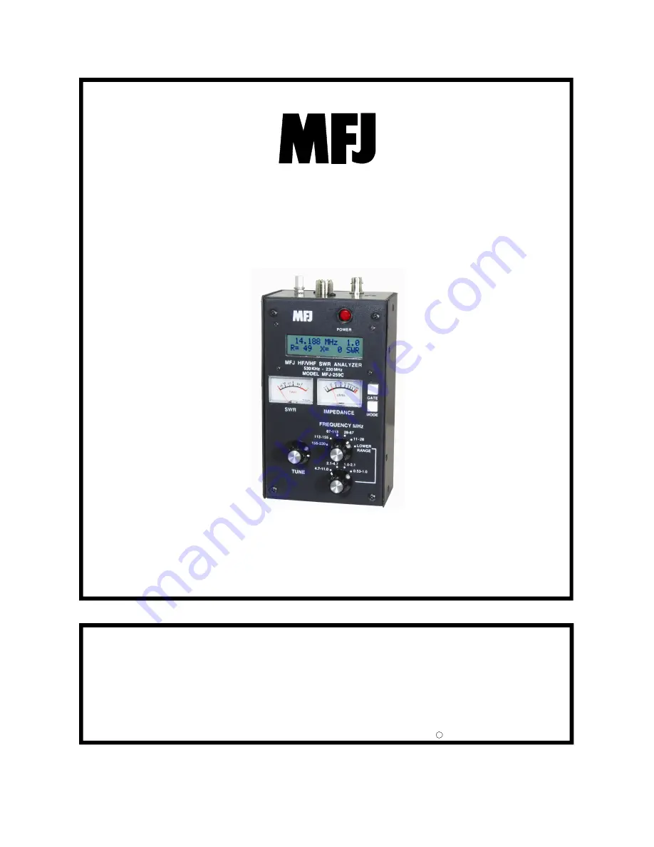
Model MFJ-259C
VERSION C1
HF/VHF SWR Analyzer


