Meyer Sound UPA-1P Operating Instructions Manual Download Page 1

Operating Instructions

UPA-P Series

(Serial Numbers 981000 and above)

UPA-1P and UPA-2P

Self-Powered Loudspeakers

Copyright © 1997

Meyer Sound Laboratories, Inc.

 All rights reserved

Part #: 05.054.017.01 Rev B
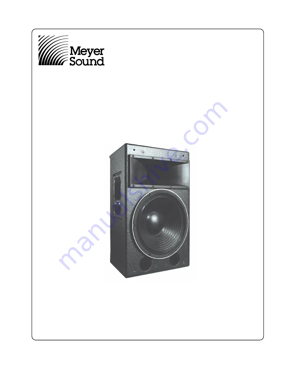
UPA-1P

Keep these important operating instructions.

Summary of Contents for UPA-1P

Page 1: ...UPA PSeries SerialNumbers981000andabove UPA 1P and UPA 2P Self Powered Loudspeakers Copyright 1997 Meyer Sound Laboratories Inc All rights reserved Part 05 054 017 01 Rev B UPA 1P Keep these important...

Page 2: ...ormity According to ISO IEC Guide and EN 45014 Safety EN60065 1994 EMC EN55103 1emmission EN55103 2immunity Name Meyer Sound Laboratories Inc Address 2832 San Pablo Avenue Berkeley California 94702 22...

Page 3: ...at which the sound pressure at a given frequency decreases to half 6 dB its on axis amplitude Specifying beam width using the 6 dB points has been proposed as the audio industry standard and Meyer So...

Page 4: ...depends on the operating level and how low the voltage drops The unit turns off if the voltage does not increase above 88V for 1 to 5 seconds If the UPA P shuts down due to brownout the power supply...

Page 5: ...rds from electrical shock Do not operate the unit with worn or frayed cables replace them immediately If the UPA P will be installed outdoors contact Meyer Sound for information about the rain hood an...

Page 6: ...nt field diagnostic tool that re movestheguessworkfromtroubleshootingduringaper formance All Meyer loudspeakers with RMS can be inte grated on the same network Installing an RMS module requires only a...

Page 7: ...nut plates blank plates if no rigging brackets are requested NOTE Units with nut plates are rated for the weight of one cabinet only Rigging load ratings assume a straight tensile pull and that the ca...

Page 8: ...lanar to one half space loaded USW 1P were designed to produce a flat system frequency response 32 Hz 18 kHz when the same full range signal is sent to all speakers It is impor tant to emphasize that...

Page 9: ...Audio Input Module This optional module described on page 6 of this user guide allows for level control on the user panel of the UPA Verifying Driver Polarity Incorrectdriverpolarityimpairssystemperfo...

Page 10: ...inated 1 Make sure the XLR cable is securely fastened to the XLR audio input connector 2 Send the audio signal to another speaker to insure that the level is within the proper range Turn the source le...

Page 11: ...hermallyoverloaded Thelimiterthresholdhasdropped to a safe level so the audio level is reduced 1 Make sure there is enough clearance above below and behind the unit 2 Make sure there is sufficient air...

Page 12: ...sgebildetemKundenienstpersonaldurchgef hrt werden Pour r duire le risque d lectrocution d brancher la prise principaledel haut parleur avantd installerlec bled interface allant l audio Nerebrancherleb...

Page 13: ...l Modules User Panel with RMS option and Standard Looping Audio Input Module Looping Polarity and Attenuating Input Module Summing Audio Input Module The user panel and optional modules are described...

Page 14: ...Dimensions in inches 14 3 30 14 5 12 8 7 7 2 6 7 5 22 4 22 4 C L 7 25 10 85 7 4 10 85 7 25 UPA P Top UPA P Back UPA 1P Side UPA 2P Side UPA 1P Front UPA 2P Front Center of gravity represented by...

Page 15: ...Notes...

Page 16: ...Meyer Sound Laboratories Inc 2832 San Pablo Avenue Berkeley California 94702 Telephone 510 486 1166 FAX 510 486 8356 E mail techsupport meyersound com http www meyersound com Contact Information...

Reviews: