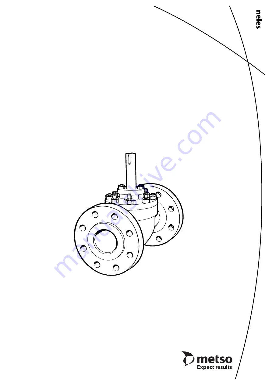
BALL VALVE
Series Top5
®
Installation, Maintenance andOperating Instructions
1 T5
71 en •
12/2008
Page 1: ...BALL VALVE Series Top5 Installation Maintenance and Operating Instructions 1 T5 71 en 12 2008 ...
Page 2: ...tive owners Table of Contents 1 GENERAL 3 1 1 Introduction 3 1 2 Valve structure 3 1 3 Markings 3 1 4 Valve approvals 4 1 5 CE marking 4 1 6 Recycling and disposal 4 1 7 Safety precautions 4 2 TRANSPORTATION RECEPTION AND STORAGE 5 3 INSTALLATION IN THE PIPELINE 5 4 COMMISSIONING 5 5 SERVICING 5 5 1 Gland packing 6 5 2 Dismantling the valve 6 5 3 Assembly 6 6 TESTING THE VALVE 10 7 INSTALLING THE ...
Page 3: ...he body shows the tight direction Identification plate markings 1 Body material 2 Stem material 3 Trim material 4 Seat material 5 Maximum and minimum operating temperatures 6 Maximum shut off pressure differential temperature 7 Pressure class 8 Type designation 9 Valve manufacturing parts list no 10 Model The type designation is explained in Metso standard S389 An extract of the standard is shown ...
Page 4: ...imitations Exceeding the limitations marked on the valve may cause damage and lead to uncontrolled pressure release Damage or personal injury may result CAUTION Do not dismantle the valve or remove it from the pipeline while the valve is pressurized Dismantling or removing a pressurized valve will result in uncontrolled pressure release Always isolate the rele vant part of the pipeline release the...
Page 5: ... mantled without detaching the valve from the pipeline Check that the indicator arrow on the actuator is paral lel to the ball flow opening The actuator must not touch the pipeline or any perma nent structures because pipeline vibration may dam age it or interfere with its operation If the pipeline drawings show a support for the actuator the support must be installed Make sure that the valve is i...
Page 6: ...stem key slot with tape a plastic bag or other similar material that protects the O ring when you push the gland over the key slot 5 2 Dismantling the valve Remove the actuator and the actuator mounting shelf Remove the key 10 Check that there are no burrs on the edges of the key slot Loosen the gland packing by unscrewing the nuts 18 Remove the hexagon nuts 16 on the bonnet Lift the bonnet You ma...
Page 7: ... order compared 5 3 1 1 A seat Figure 13 Check the sealing surfaces Install the back seal 130 on the seat 7 Install the ring 129 Install the spring 62 into the seat body Install the support ring 35 Spread some anticorrosive agent e g Cortec VCI 369 in the seat recess of a carbon steel body Push the seat into its place 5 3 1 2 F seat Figure 14 Check the sealing surfaces Check the sealing surfaces a...
Page 8: ...O ring 63 with silicone grease before installation Install the O ring 63 Install the support ring 64 into its groove Cut the ribbon ends diagonally to make a flexible seam Only in the Fire Safe version Install the back seal 130 and the ring 129 See Fig 17 Install the spring 62 into the seat body 7 Install the spring support ring 131 5 3 1 5 E1 seat Figure 18 Check the sealing surfaces Install the ...
Page 9: ...to the bonnet and the body using a nail punch 5 3 3 Installing the ball If the ball surface has deep scratches that cannot be removed using an abrasive cloth or if it is not com pletely round you should send the ball to the manufac turer for repair Adjust the seat to the ball by lapping them together with diamond powder before you install the ball and the seat into the body Install the ball into t...
Page 10: ... series actuator Drive the actuator piston to the extreme outward end and turn the valve into the closed position Clean the stem bore and file off any burrs If a coupling is needed between the actuator and the valve stem install it into the stem bore Lubri cate the coupling and stem bore Note the cor rect position The line at the end of the stem indicates the direction of the ball flow bore Fasten...
Page 11: ...ors are used in applications where valve opening or closing movement is needed in case the air supply is interrupted The BJ B1J type is used for spring to close operation the spring pushes the pis ton towards the cylinder end the extreme outward position In turn the BJA B1JA type is used for spring to open operation the spring is between the piston and the cylinder end and pushes the piston toward...
Page 12: ...12 1 T5 71 en 9 EXPLODED VIEW ...
Page 13: ...ion Spare part category 1 1 Body 3 1 Ball 3 4 1 Thrust bearing 3 5 1 Trunnion bearing 3 7 1 Seat 2 8 1 Bonnet 9 1 Gland 10 1 Key 3 11 Stud 12 Stud 14 Stud 15 Hexagon nut 16 Hexagon nut 18 Hexagon nut 19 1 Identification plate 20 2 Screw 27 1 Lock ring 35 1 Support ring 2 60 1 Bearing 3 61 1 Bearing 3 62 1 Spring 2 63 1 O ring 64 1 G seat 2 Support ring 65 1 Gasket 1 69 Gland packing 1 75 1 O ring ...
Page 14: ... T5D06 B1C20 150 473 317 5 102 840 575 680 270 397 97 215 1 2 188 T5D06 B1C25 150 473 317 5 102 1040 710 735 310 415 121 265 1 2 245 T5D08 B1C20 200 568 381 125 840 575 755 270 440 97 215 1 2 312 T5D08 B1C25 200 568 381 125 1040 710 815 310 465 121 265 1 2 369 T5D08 B1C32 200 568 381 125 1330 910 895 350 505 153 395 3 4 489 T5D10 B1C25 250 708 444 5 152 1040 710 865 310 480 121 265 1 2 445 T5D10 B...
Page 15: ... B1C32 400 1108 685 8 254 1330 910 1300 350 755 153 395 3 4 1478 T5F16 B1C40 400 1108 685 8 254 1660 1150 1400 370 805 194 505 3 4 1673 T5F16 B1C50 400 1108 685 8 254 1970 1350 1505 415 855 242 610 1 2058 Type DN A _B _D F G H I J V X NPT kg T5D01 B1J B1JA8 25 197 124 25 560 420 320 220 192 43 135 3 8 27 T5D01 B1J10 25 197 124 25 650 490 350 225 198 51 175 3 8 40 T5D015 B1J B1JA8 40 235 155 4 38 5...
Page 16: ...165 1 50 540 375 410 225 245 51 135 3 8 53 T25F02 B1C13 50 292 165 1 50 635 445 440 235 260 65 175 3 8 68 T25F03 B1C13 80 356 209 5 76 635 445 500 235 300 65 175 3 8 107 T25F03 B1C17 80 356 209 5 76 770 545 530 255 315 78 215 1 2 130 T25F03 B1C20 80 356 209 5 76 840 575 570 270 337 97 215 1 2 145 T25F04 B1C17 100 432 273 1 102 770 545 625 255 375 78 215 1 2 205 T25F04 B1C20 100 432 273 1 102 840 5...
Page 17: ...154 1 840 575 645 270 397 97 215 1 2 198 T4D06 B1C25 150 559 172 122 102 154 1 1040 710 700 310 415 121 265 1 2 265 T4D08 B1C20 200 660 223 140 125 202 7 840 575 705 270 440 97 265 1 2 283 T4D08 B1C25 200 660 223 140 125 202 7 1040 710 765 310 465 121 265 1 2 350 T4D08 B1C32 200 660 223 140 125 202 7 1330 910 845 350 505 153 395 3 4 480 T4D10 B1C25 250 787 278 170 152 254 4 1040 710 810 310 480 12...
Page 18: ...0 991 413 275 254 363 6 1330 910 1230 350 755 153 395 3 4 1260 T4F16 B1C40 400 991 413 275 254 363 6 1660 1150 1335 370 805 194 505 3 4 1450 T4F16 B1C50 400 991 413 275 254 363 6 1970 1350 1435 415 855 242 610 1 1840 Type DN A _B C _D _E F G H I J V X NPT kg T4D01 B1J B1JA8 25 210 36 38 25 26 6 560 420 305 220 192 51 175 3 8 33 T4D01 B1J10 25 210 36 38 25 26 6 650 490 325 225 198 65 215 3 8 45 T4D...
Page 19: ... 375 225 245 51 135 3 8 49 T35F02 B1C13 50 292 91 68 50 73 7 635 445 425 235 260 65 175 3 8 63 T35F03 B1C13 80 356 117 90 76 97 1 635 445 485 235 300 65 175 3 8 97 T35F03 B1C17 80 356 117 90 76 97 1 770 545 515 255 315 78 215 1 2 120 T35F03 B1C20 80 356 117 90 76 97 1 840 575 550 270 337 97 215 1 2 135 T35F04 B1C17 100 432 172 122 102 146 3 770 545 610 255 375 78 215 1 2 185 T35F04 B1C20 100 432 1...
Page 20: ... 971 4 883 6836 www metso com automation 20 1 T5 71 en 12 TYPE CODING TOP ENTRY BALL VALVE Series Top 5 1 2 3 4 5 6 7 8 9 10 TS F B 04 A A F 03 01 1 TRIM OPTIONS V PORT Q TRIM 2 SERIES T5 Reduced bore flanged T4 Reduced bore weld ends T25 Full bore flanged T35 Full bore weld ends 3 PRESSURE RATING D ASME class 300 F ASME class 600 4 CONSTRUCTION E General PTFE bearings B High and low temperature m...