8 PZ
70 en • 5/2
0
1
8
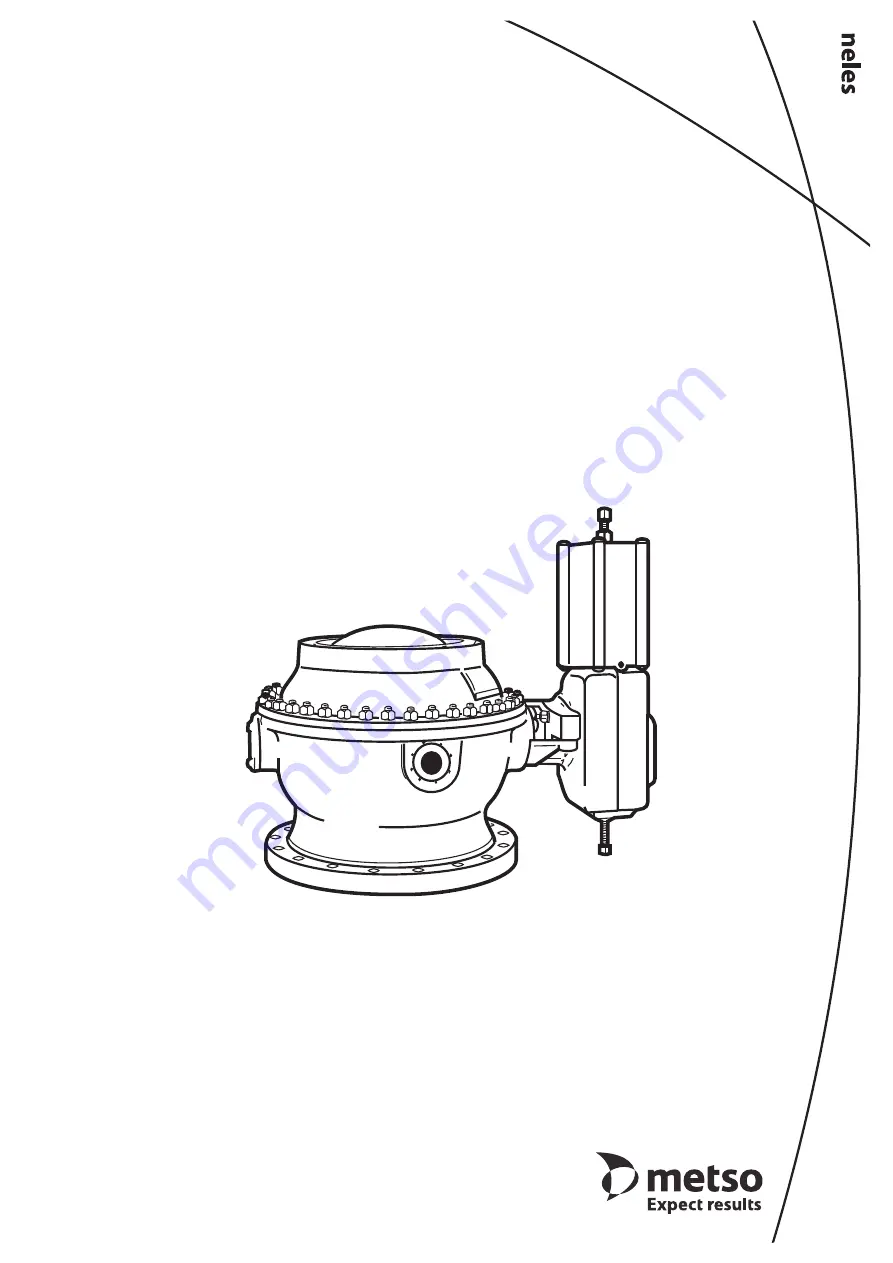
CAPPING VALVE
Series PZ
Installation, Maintenance andOperating Instructions
Page 1: ...8 PZ 70 en 5 2018 CAPPING VALVE Series PZ Installation Maintenance and Operating Instructions ...
Page 2: ...Specifications 3 1 5 Valve performance 4 1 6 Valve approval 5 1 7 Recycling and disposal 5 1 8 Safety precautions 5 2 TRANSPORTATION RECEPTION AND STORAGE 5 3 INSTALLATION AND COMMISSIONING 5 3 1 General 5 3 2 Mounting the valve on the digester 6 3 3 The actuator 6 3 4 Commissioning 6 4 MAINTENANCE 6 4 1 General 6 4 2 Changing the gland packing 6 4 3 Bearings 5 22 7 4 4 Body joint 7 4 5 Ball and s...
Page 3: ... electrical interlocking device consists of pressure trans mitters 2 pcs relays solenoid valves and limit switches See the application report no 2611 01 02en 12 2011 Safety interlocking system ACC The mechanical interlocking device B1CP is based on a spring return cylinder which operates a lever inside the actuator This lever locks the valve in the closed position These devices prevent the valve f...
Page 4: ...ss and smooth operation However in practice it is difficult to totally pre vent chips sawdust dirt or any other contaminants from adhering to the ball surface particulary during the cooking sequence temp about 175 C 347 F causing possible ball surface damages Metso realizes that some mills may require a water wash spray to the ball surface and others may require a water bed Information on these ad...
Page 5: ...ult in uncontrolled pressure release Damage to equipment or personal injury may result CAUTION Do not remove or dismantle a pressurized valve Removing or dismantling a pressurized valve leads to uncontrolled pressure release Always release pressure and remove the media from the valve before removing or dismantling it Protect yourself and the environment from poisonous or otherwise harmful substanc...
Page 6: ... your local Metso experts During this periodic inspection the parts detailed in the Spare Part Set should be replaced Time in storage should be included in the inspection interval Maintenance can be performed as presented below For maintenance assistance please contact your local Metso office The part numbers in the text refer to the exploded view and to the parts list in Section 8 unless otherwis...
Page 7: ...loops delivered with the valve for lifting Dismantle the valve on a clean level cardboard or wooden underlay Lower the valve onto the underlay if you have removed the whole valve from the digester Turn the ball to the closed position Detach the actuator using the extractor see Chapter 6 Dismantle the upper body half 1 Fasten the lifting strap through the ball and keep it adequately tightened Remov...
Page 8: ...the packing groove with the gland Position the cut ends of the rings at a 90 angle to each other and at a 45 angle to the flow port Set the outer ring 34 and the gland 6 into place and tighten the nuts 17 lightly Set the body gasket 26 in place The gasket must be replaced each time the valve is dismantled Install the tilting device Replace the bearings 24 and ring 41 of the console 7 Slide the rin...
Page 9: ...ion when the valve is closed Turn the studs into the actuator before sliding the actuator onto the stem Slide the actuator into position carefully Adjust the open and closed position limits 5 1 Adjusting open and closed positions The open and closed position limits of the valve are adjusted with the stop screws on the actuator see Fig 18 Adjusting the closed position Using a soft pencil draw two l...
Page 10: ...allel After the adjustment lock the retaining screws and seal them e g with Loctite 225 Fig 18 Actuator stop screws Fig 19 Drawing the marking lines Table 3 G dimensions Valve G1 mm G2 mm PZ 500 20 52 2 1 30 1 2 PZ 600 24 62 2 5 35 1 4 PZ 750 30 69 2 8 35 1 4 Closed position stop screw Open position stop screw Fig 20 G1 measure Fig 21 G2 measure ...
Page 11: ... ordering spare parts always give the following infor mation valve type designation from the identification plate or valve documents parts list number or number of this manual part number name of the part and number of pieces required Table 4 Extractors Valve actuator Extractor PZ 500 BCP32 8546 5 PZ 600 BCP32 8546 5 PZ 750 BCP40 8546 6 NOTE Use original spare parts to ensure that the valve functi...
Page 12: ... 8 1 Bonnet 9 1 Spiral gasket x 10 Screw 11 Stud 12 2 Stud 13 2 Stud 13a 2 Lock nut 16 Nut 17 2 Nut 18 2 Nut 20 Disc spring 21 1 Key Item Qty Description Recommended spare part 22 1 Bearing bushing 24 1 Bearing strip x 25 2 Sealing cord x 26 1 Seal strip x 28 Packing ring x 29 1 Identification plate 31 4 Stud 32 2 Adjusting plate kit 33 4 Lifting eye bolt 34 2 Support ring 35 Nut 38 1 Support 38 1...
Page 13: ...Casting gland 068 2 Stud 069 2 Retainer plate 070 2 Disc spring set 071 2 Hexagon nut 072 1 Cylinder base 072A 1 Sticker LOCK 073 1 Cylinder pipe 074 1 Cylinder end 074A 1 StIcker RELEASE 075 2 Piston 076 1 O ring x 077 1 O ring x 078 2 O ring x 079 1 Bearing strip x 080 2 Piston ring x 081 1 Hexagon screw 082 4 Hexagon screw 083 1 O ring 084 1 Hexagon nut 085 8 Hexagon screw 086 1 Lock nut 087 1 ...
Page 14: ... DEVICE LIMIT SWITCH CAPPING VALVE 4 switches LIMIT SWITCH JAMMER 5 3 WAY SOLENOID VALVE DUAL COIL 5 2 WAY SOLENOID VALVE SINGLE COIL FILTER REGULATOR CLOSE UNLOCK LOCK OPEN CLOSE RELEASE LOCK JAMMER IMPORTANT NOTICE ENERGIZE SOLENOID VALVE 11 A BEFORE ANY VALVE OPERATION AND KEEP IT ENERGIZED UNTIL VALVE FULLY CLOSED DURING COOKING PERIOD DE ENERGIZED VALVE AND ACTUATOR SHOWN IN FULLY CLOSED POSI...
Page 15: ...80 D 890 1080 930 600 450 1330 910 860 1 42 1660 1150 505 194 1200 B1C 40 2600 Valve Main dimensions in inch Pneumatic actuator type Weight lbs Type Size Lower flange A A1 B C L U1 F G X V J UNC Depth PZ 500 AK 20 19 29 D 20 47 25 19 D 26 77 28 74 24 80 15 75 11 81 36 22 24 61 23 23 3 4 1 50 52 36 35 83 15 55 6 02 33 07 B1C 32 2750 PZ 600 AK 24 22 83 D 23 23 28 34 D 29 13 34 25 30 31 18 90 14 96 4...
Page 16: ... valve series PZ 1 2 3 4 5 6 7 8 PZ K S 600 800 A R V 1 Product series Construction Pressure rating PZ Ball valve lower body half with flange to be specified in order Upper body half with 16 pcs tapped holes with metric threads or unified threads starting from center line Body pressure rating PN16 ANSI class 150 2 Connections Special construction K 2 pcs PN16 DN 80 connections in lower body half C...