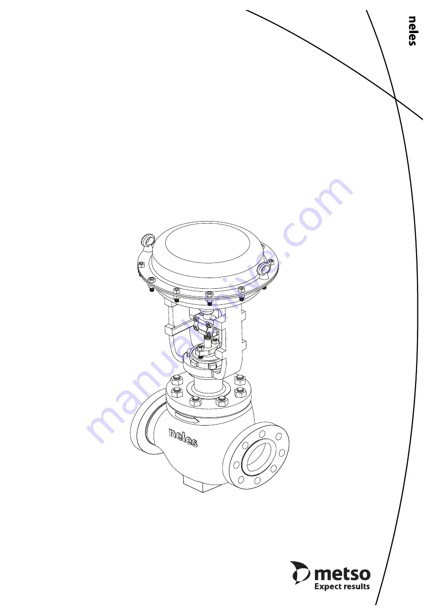
Control ValvesGlobe-Omega, Multistage trim
Series GM
Installation, Maintenance andOperating Instructions
4
G
V
70 en •
2
/2
017
Page 1: ...Control Valves Globe Omega Multistage trim Series GM Installation Maintenance and Operating Instructions 4 GV 70 en 2 2017 ...
Page 2: ...Recycling and disposal 3 1 7 Safety precautions 4 2 TRANSPORTATION RECEPTION AND STORAGE 4 3 VALVE INSTALLATION 4 3 1 General 4 3 2 Installation into the pipeline 4 3 3 Hydrostatic testing and Line flushing 5 3 4 Control valve assembly 5 3 5 Valve insulation 5 4 MAINTENANCE 5 4 1 General 5 4 2 Gland packing adjustment 5 4 3 Replacing the gland packing 6 4 4 Replacing the trim and body reassembly 6...
Page 3: ...5 08 01 03 05 ANSI ISA 75 08 06 Long Body rating Class 150 to Class 4500 PN 10 to PN 450 Max pressure differential acc to pressure class Temperature range 196 to 593 C depending on the body materials and bonnet type Flow direction indicated by an arrow on the body normally flow to open Actuator mounting threaded bonnet with yoke nut or bolted yoke Stem connection clamp with bolts nuts Dimensions s...
Page 4: ...nces Make sure that no medium can enter the pipeline during valve maintenance Failure to do this may result in damage or personal injury CAUTION Beware of the plug movement Keep fingers other parts of the body tools and other objects out of the open flow port Leave no foreign objects inside the pipeline When the valve is actuated the plug functions as a cutting device Close and detach the actuator...
Page 5: ...aintenance and operating manuals 3 5 Valve insulation If necessary the valve may be insulated Insulation must not continueabove the upperlevelof the valve body see Fig 5 Fig 5 Insulation of the valve 4 MAINTENANCE 4 1 General The Neles series GM Omega multistage trim valves require no regular maintenance However check the gland packing for leakage This section outlines the maintenance that can be ...
Page 6: ...he valve is pressurised NOTE The trim set consists of the seat ring valve plug and stem disk stack cage guide and gaskets for seat ring and bonnet Standard construction Low Emission with Live Load Spring Table1 Requiredtorquesforbonnetnuts Valve Size Rating ANSI Bonnet Stud Bolts Required Torques 5 allowable mm in Size Q ty Carbon Steel Bolts St Steel Bolts Nm lbf ft Nm lbf ft 50 2 150 300 1 2 13U...
Page 7: ...here is damage scratches or grooves it should be replaced or repaired Insert the cleaned pilot spring 77 into the upper side of main plug Install the pilot plug 73 stem 72 on the spring 77 Install the pilot cover 74 and fasten the pilot bolts 75 keep in balance Install wire 76 for connecting the all pilot bolts due to prevent loose on operation Fig 9 Different trim designs CAUTION Do not strongly ...
Page 8: ...tuatorreplacement mounting forReverse air to open stem retract actuator Fig 11 Mount the new or repaired actuator on top of the bonnet using a suitable lifting device Insert the yoke nut and tightly fasten the yoke by turning the yoke nut clockwise using tightening tools Connect air line and accessories Lift the top stem 18 using by specified air pressure Adjust stem length after clamping clamp 1 ...
Page 9: ...r information on their installation maintenance and operation 7 TOOLS Removal of the actuator L wrench set mm hex socket wrench set chisel and hammer 10 pound drivers 8 ORDERING SPARE PARTS When ordering spare parts always include the following information type code sales order number serial number number of the parts list part number name of the part and quantity required This information can be ...
Page 10: ...E 12 DISK SPRING ASS Y 13 STUD 14 STUD 16 CAGE GUIDE 17 HEXAGON NUT 18 HEXAGON NUT 19 IDNTIFICATION PLATE 19A RIVET 21 LANTERN RING 25 DISK STACK 63 SEAT GASKET X 64 SEAL RING X 65 BODY GASKET X 67 PACKING SPACER 69 PACKING RING X 71 PILOT MAIN PLUG 73 PILOT PLUG 74 PILOT COVER 75 PILOT BOLT 76 PILOT WIRE 77 PILOT SPRING Located inside the pilot main plug see Fig 8 at page 7 Live Load Application ...
Page 11: ...0 150 485 520 560 25 4 31 8 34 9 431 8 450 8 489 12 16 20 905 955 1020 14 889 927 972 385 385 385 616 740 210 535 585 605 28 6 31 8 38 1 476 3 514 4 527 12 20 20 1170 1230 1311 16 1016 1057 1108 440 440 440 692 820 220 595 650 685 28 6 34 9 41 3 539 8 571 5 603 2 16 20 20 1380 1460 1587 900 1500 UNIT mm Dimension Size A B C D E F G H Weight kg 900 1500 900 1500 STD EXT COMMON 900 1500 900 1500 900...
Page 12: ...irect acting actuator VDD UNIT mm With handwheel Size A2 Bd Br D A3 Ed Er C2 Weight kg 25 255 348 373 NPT 1 4 312 110 170 225 22 29 295 391 416 NPT 1 4 312 122 182 251 28 37 375 464 489 NPT 1 4 342 141 201 284 43 48 486 652 677 NPT 1 4 464 144 244 381 119 55 566 695 720 NPT 1 4 464 144 244 381 145 NOTE 1 Br refers to reverse acting actuator VDR 2 Bd refers to direct acting actuator VDD VDD Direct ...
Page 13: ... 830 Ø560 225 560 PT 1 2 192 242 995 390 70 145 840 Ø560 235 560 PT 1 2 195 246 1025 420 80 145 850 Ø560 245 560 PT 1 2 198 251 1055 450 90 145 860 Ø560 255 560 PT 1 2 201 256 1085 480 100 145 870 Ø560 265 560 PT 1 2 203 261 1115 510 120 145 890 Ø560 285 560 PT 1 2 209 270 1175 570 140 145 910 Ø560 305 560 PT 1 2 215 279 1235 630 180 145 950 Ø560 345 560 PT 1 2 227 298 1355 750 Size 60 UNIT mm Str...
Page 14: ...15 Ø560 225 845 616 PT 1 2 252 303 1280 390 70 145 1125 Ø560 235 845 616 PT 1 2 255 308 1310 420 80 145 1135 Ø560 245 845 616 PT 1 2 258 313 1340 450 90 145 1145 Ø560 255 845 616 PT 1 2 261 318 1370 480 100 145 1155 Ø560 265 845 616 PT 1 2 263 322 1400 510 120 145 1175 Ø560 285 845 616 PT 1 2 269 332 1460 570 140 145 1195 Ø560 305 845 616 PT 1 2 275 341 1520 630 180 145 1235 Ø560 345 845 616 PT 1 ...
Page 15: ...S9 A351 gr CF3 S1 A351 gr CF3M YY Special 7 BEARINGS TRUNNION THRUST BEARING X Not Applicable Y Special 8 PLUG MATERIAL P2 SUS 420J2 YY Special 9 PLUG APPLICATION X Not Applicable A Cobalt based alloy Optional plug application C Hard chrome D Cobalt based alloy HCr Y Special 10 STEM MATERIAL BC 630 SS HCr YY Special 11 SEAT TYPE S1 Single metal seat YY Special 12 SEAT DISK STACK MATERIAL Seat Disk...
Page 16: ...valve stroke in mm 4 The other Cvs and trim types please contact Metso 20 Trim type 21 Trim characteristic 22 RATED Cv Sign Sign Sign Description Body Size and stroke 1 Srk 1 1 2 Srk 2 Srk 3 Srk 4 Srk 6 Srk 8 Srk 10 Srk 12 Srk 14 Srk 16 Srk A Balanced plug type L Linear FG Full capa Gas 7 30 16 30 26 40 54 50 84 50 146 60 252 70 384 80 560 100 770 120 1020 140 P Pilotbalancedplug type Q Quick open...