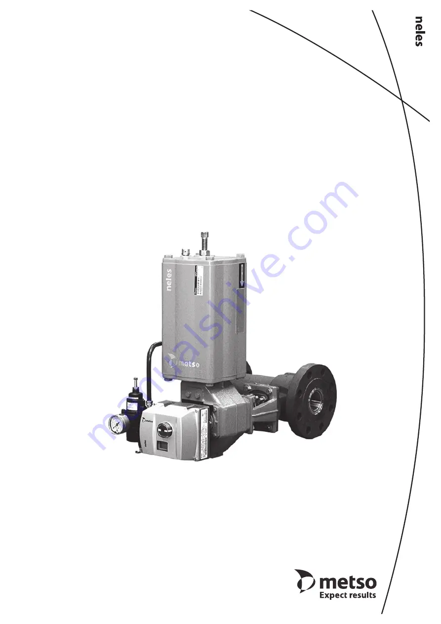
FINETROL®Eccentric rotary plug control valve
Installation, Maintenance andOperating Instructions
5
FT 70
en • 10
/20
1
6
Page 1: ...FINETROL Eccentric rotary plug control valve Installation Maintenance and Operating Instructions 5 FT 70 en 10 2016 ...
Page 2: ... 4 3 Changing the packing 7 4 4 Detaching the actuator 8 4 5 Removing the valve from the pipeline 8 4 6 Changing the seat 9 4 7 Dismantling the valve 10 4 8 Cleaning and inspection of removed parts 10 4 9 Assembly 11 4 10 FL low capacity valve 11 5 TESTING THE VALVE 13 6 INSTALLING AND DETACHING THE ACTUATOR 14 6 1 General 14 6 2 Installing the Quadra Powr actuators 14 6 3 Installing the B1C serie...
Page 3: ... Valve markings The valve has an identification plate A manufacturing number specific to each valve has been stamped on the side of the actuator plane The identification plate is normally located in the spherical area outer diameter of the pipe flange on the stem side opposite to the seat When using a small identification plate with a small size valve the plate is installed to the valve body neck ...
Page 4: ...uipment and has been marked according to the Directive 1 7 Recycling and disposal Most valve parts can be recycled if sorted according to material Most parts have material marking A material list is supplied with the valve In addition separate recycling and disposal instructions are available from the manufacturer A valve can also be returned to the manufacturer for recycling and disposal against ...
Page 5: ...age or personal injury may result CAUTION Do not dismantle the valve or remove it from the pipeline while the valve is pressurized Dismantling or removing a pressurized valve will result in uncontrolled pressure release Always isolate the relevant part of the pipeline release the pressure from the valve and remove the medium before dismantling the valve Be aware of the type of medium involved Prot...
Page 6: ...r must not touch the pipeline because pipeline vibration may damage it or interfere with its operation In some cases for instance when the actuator is exception ally large or when there is lot of piping vibration it may be advisable to support the actuator Contact Metso s Flow Control for more instructions 3 4 Commissioning Ensure that no dirt or foreign objects are left inside the valve or pipeli...
Page 7: ... the stem The studs 14 need not be detached Remove the packing rings 69 from around the stem using a pointed instrument or a detaching tool Do not damage the surfaces of the stem and the pack ing ring counterbore Place the new packing rings 69 over the stem Do not damage the sealing lips of the V rings in the stem splines Use the gland follower 9 as a tool for pushing the packing rings all the way...
Page 8: ...Detaching the actuator It is generally most convenient to detach the actuator and its auxiliary devices before removing the valve from the pipeline If the valve package is small or if it is difficult to access it may be more practical to remove the entire pack age at the same time See Section 6 for details of detaching actuators 4 5 Removing the valve from the pipeline After you have detached the ...
Page 9: ...r handlever using torque value specified in Table 11 Remove the locking shoulders of the insert 2 and unscrew the insert using a special tool see exploded view and parts list in Section 10 The special tool is available from the valve manufacturer Remove the back seal 63 and unscrew the seat 7 from the valve body Replace the insert 2 seat 7 and back seal 63 with new parts Centre the plug 3 in the c...
Page 10: ...g Detach the upper bearing 15 from the body by tap ping it through the stem bore using a suitable bar Do not use the stem Detach the lower bearing using a special tool and drive shaft Set up the tool as illustrated in Fig 17 Use a soft hammer to carefully hit shaft end This will detach the bearing 4 7 2 FL series Turn the valve into closed position and place it verti cally the seat side pipe flang...
Page 11: ...stem with the hand lever using torque specified on Table 11 At the same time tighten the insert 2 with a spanner wrench using torque specified on Table 4 A light can be shined behind the plug to determine the best possible alignment The best alignment is when the least amount of light can be seen between the plug and seat Lock the insert by hitting it with a nail punch to make juts over two of the...
Page 12: ...correctly aligned The movement should be smooth Install the back seal 63 into the insert 2 Screw the insert 2 onto the threads of the bushing 35 Tighten the insert with a seat retainer tool The torques are given in Table 4 Lock the insert by hitting it with a nail punch to make juts over two notches of four available on the body 4 10 3 Dismantling the valve Remove the valve from the pipeline and d...
Page 13: ... bushing back so that the eccentric seat can be turned into the right position Observe the position using the mark made ealier Hold the seat with an Allen key and screw the bushing with a wrench Move the Allen key carefully back and forth to find the position where the seat is most loosen When you find the right position hold the seat in that position and tighten the bushing until its threads are ...
Page 14: ...open Clean the stem bore and lubricate it Connect the supply pressure to the actuator Oper ate the actuator until it reaches closed position Turn the plug closed position The line at the end of the stem shows the position Push the actuator carefully onto the valve stem Make sure that the installation position is correct Avoid forcing it since this may damage the plug and seat Increase the supply p...
Page 15: ...lies not to low Cv valves Check the stop screw thread tightness The threads must be sealed using an appropriate non hardening sealant e g Loctite 225 Check that the actuator is functioning correctly Drive the actuator piston to both cylinder ends and check the plug position and its movement with respect to the actuator close clockwise open coun terclockwise The valve should be closed when the pist...
Page 16: ...s adapted to the valve shaft with a separate bushing The bushing II II is a two piece cone shaped bushing which is tightened firmly with a tightening screw I around the valve shaft The bushing and the tightening screw are inserted to actuator drive shaft according to Fig 24 Cylindri cal pins III are inserted in the bushing slots and these must be directed into the corresponding slots in the actuat...
Page 17: ...rface conforms to Table 7 see Fig 25 The drive shaft will automatically find its correct position if the installation tool H061904 see Fig 25 is used The installation tool is attached instead of the coupling plate using M4 screws with the drive shaft in lower position before the valve is installed Tighten the nut of the tool in such a way that the tool pulls the drive shaft to the uppermost positi...
Page 18: ...ommended to use a suitable bushing from the tool set H061544 between the tightening screw I and drive shaft The bushing dimensions are given in Table 9 Detach the actuator finally from the valve after the screws that attach the actuator to the valve have been removed Observe the respective positions between the actua tor and valve and also between the key and keyway before removal Attaching the ac...
Page 19: ...s Torque Nm Metal seat Soft seat 25 15 15 40 20 20 50 40 40 80 62 70 100 155 170 150 300 350 200 550 600 250 600 700 Product ID DN 25 1 975800 DN 40 1 975780 DN 50 2 975760 DN 80 3 975740 DN 100 4 975720 DN 150 6 975140 Product ID Hole Ø120 X lenght 780 mm H108850 Hole Ø105 X lenght 780 mm H108848 Hole Ø95 X lenght 770 mm H108847 Hole Ø85 X lenght 760 mm H108845 Hole Ø75 X lenght 555 mm H108844 Ho...
Page 20: ...element Spares for the full overhaul All parts from the categories 1 2 and 3 Item Qty Description Spare part category 1 1 Body 2 1 Insert 2 3 1 Plug 3 3a 1 Plug with Q plate 3 5 1 Stem one piece shaft 3 7 1 Seat 2 8 1 Bonnet 9 1 Gland 10 1 Key 13 4 Stud 14 2 Stud 15 1 Upper bearing 3 16 1 Lower bearing 3 17 4 Hexagon nut 18 2 Hexagon nut 19 1 Identification plate 63 1 Back seal 2 66 1 Bonnet seal ...
Page 21: ...s from the categories 1 2 and 3 25 32 14 4 5 6 7 3 8 12 26 10 19 17 1 24 35 30 14 16 11 20 9 13 Item Qty Description Spare part category 1 1 Body 3 1 Ball 3 4 1 Bushing 2 5 1 Spring 2 6 1 Back seal 2 7 1 Seat 2 8 1 Support ring 2 9 Gland 10 Blind flange 11 1 Drive shaft 3 12 1 Shaft 3 13 1 Key 3 14 2 Cylindrical pin 3 16 1 Upper bearing 3 17 1 Lower bearing 3 19 1 Gasket 1 20 1 Gland packing 1 24 ...
Page 22: ...2 13 88 229 9 02 665 26 18 96 212 100 4 5 194 7 62 254 10 00 720 28 35 138 304 352 13 88 229 9 02 710 27 95 146 322 150 6 5 229 9 00 318 12 52 795 31 30 154 339 451 17 75 280 11 02 775 30 51 170 374 ASME300 25 1 FL 1 102 4 00 124 4 88 388 15 27 20 5 45 2 25 1 1 102 4 00 124 4 88 405 15 94 19 42 197 7 75 124 4 88 405 15 94 20 44 25 1 2 102 4 00 124 4 88 420 16 54 27 60 197 7 75 124 4 88 420 16 54 2...
Page 23: ...59 175 6 89 3 8 100 4 12 97 3 82 651 25 63 406 15 98 695 27 36 245 9 65 620 24 41 800 31 50 215 8 46 1 2 150 6 16 114 5 4 51 772 30 39 461 18 15 750 29 53 260 10 24 760 29 92 990 38 98 265 10 43 1 2 200 8 20 121 5 4 78 996 39 21 565 22 24 836 32 91 275 10 83 935 36 81 1200 47 24 395 15 55 3 4 250 10 25 148 5 5 85 1159 45 63 634 24 96 905 35 63 310 12 20 1200 47 24 1530 60 24 505 19 88 3 4 Valveand...
Page 24: ...ASME300 25 01 FL EC05 102 4 02 124 4 88 329 12 95 12 27 25 01 EC05 102 4 02 124 4 88 345 13 58 14 31 197 13 58 124 4 88 345 13 58 15 33 EC07 102 4 02 124 4 88 371 14 61 16 35 197 14 61 124 4 88 371 14 61 17 37 40 015 EC05 114 4 49 155 6 10 376 14 80 17 37 235 14 80 155 6 10 376 14 80 18 40 EC07 114 4 49 155 6 10 402 15 83 19 42 235 15 83 155 6 10 402 15 83 20 44 50 02 EC07 124 4 88 165 6 50 417 16...
Page 25: ...00 1540 ASME300 25 01 FL EJ EJA05 102 4 02 124 4 88 329 12 95 14 31 25 01 EJ EJA05 102 4 02 124 4 88 345 13 58 15 33 197 7 76 124 4 88 345 13 58 16 35 EJ EJA07 102 4 02 124 4 88 371 14 61 20 44 197 7 76 124 4 88 371 14 61 21 46 40 015 EJ EJA05 114 4 49 155 6 10 376 14 80 18 40 235 9 25 155 6 10 376 14 80 19 42 EJ EJA07 114 4 49 155 6 10 402 15 83 23 51 235 9 25 155 6 10 402 15 83 24 53 50 02 EJ EJ...
Page 26: ...Steam jacket with flushing connections FTO MB Steam jacket with flushing connections FTC C1 Max Cv value 4 2 Series FL Low Cv construction size 1 DN 25 only FTO Live loaded single packing C2 Max Cv value 1 5 Series FL Low Cv construction size 1 DN 25 only FTO Live loaded single packing C3 Max Cv value 0 5 Series FL Low Cv construction size 1 DN 25 only FTO Live loaded single packing ASME ISA VALVE...
Page 27: ...10 PN16 PN25 PN40 PN63 PN100 025 PN40 PN40 PN40 M PN100 P 040 PN40 PN40 PN40 M PN100 P 050 PN16 K PN40 M N P 080 PN16 K PN40 M N P 100 PN16 K PN40 M N P 150 PN16 K PN40 M N P 200 J K L M N P 250 J K L M N P Size Pressure Flange threats pcs flange 01 600 5 8 UNC 4 02 600 5 8 UNC 2 03 600 3 4 UNC 2 04 600 7 8 UNC 2 06 600 1 UNC 2 08 600 1 1 8 8UN 2 10 600 1 1 4 8UN 2 Size mm Pressure class Flange th...
Page 28: ...01 Sorocaba São Paulo Brazil Tel 55 15 2102 9700 Fax 55 15 2102 9748 Asia Pacific Haw Par Centre 06 01 180 Clemenceau Avenue Singapore 239922 Tel 65 6511 1011 Fax 65 6250 0830 China 11 F China Youth Plaza No 19 North Rd of East 3rd Ring Rd Chaoyang District Beijing 100020 China Tel 86 10 6566 6600 Fax 86 10 6566 2583 Middle East Roundabout 8 Unit AB 07 P O Box 17175 Jebel Ali Freezone Dubai United...