Autolab/Electronic load combination
14 |
P a g e
7
– Connections to the cell
The electronic load (+) is connected to the (+ or cathode) of the cell, and the
electronic load (-) is connected to the (- or anode) of the cell.
7.1
– Connections for cell voltages ≤ 10 V
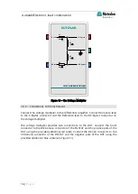
The S and RE cables of the Autolab differential amplifier are connected to the cell
under study. The S is connected to the (+) and the RE connected to the (-). The CE
and WE connections of the PGSTAT are not used.
Warning
Analog programming of the electronic load requires a modification of the FRA2
module to accept analog signal up to 10 V. A hardware and software
modification may be required. More information is provided in the Appendix 2.
Please contact Metrohm Autolab (
) or your local
distributor in case of any doubts.
∆𝐸
𝐿𝑂𝐴𝐷
=
∆𝐸
𝐴𝑈𝑇
− 𝑖𝑅
Warning
The cables connecting the electronic load to the cell must have the lowest
possible resistance and should be able to withstand high current densities.
Keep in mind that ohmic losses cannot completely be avoided. Most electronic
loads have a voltage reversal detection circuit which monitors the cell voltage
and shuts down the load when this value becomes negative or lower than a
threshold. For electronic loads that are unable to operate at low cell voltages,
the maximum current that can be drawn from the cell may be affected by
ohmic losses.
Because of ohmic losses, the apparent voltage measured by the load,
∆𝐸
𝐿𝑂𝐴𝐷
is
always smaller than the voltage measured by the Autolab (
∆𝐸
𝐴𝑈𝑇
) by a value
equal to the product of
𝑖
and
𝑅
, where
𝑅
is the total resistance of the cables:
Passing 80 A through 10 mΩ cables, leads to 800 mV ohmic drop.
Warning
Never connect the CE and WE from the Autolab PGSTAT to the cell!


