Insert new module for the Autolab 8-Series
1 |
P a g e
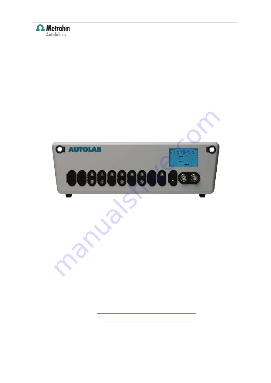
INSERT NEW MODULE FOR THE
AUTOLAB 8-SERIES
Editorial
Metrohm Autolab B.V.
Kanaalweg 29 G, 3526 KM Utrecht
The Netherlands
Tel: +31 30 2893154
Fax: +31 30 2880715
E-mail:
[email protected]
Website:
www.metrohm-autolab.com
© Copyright 2011 Metrohm Autolab


