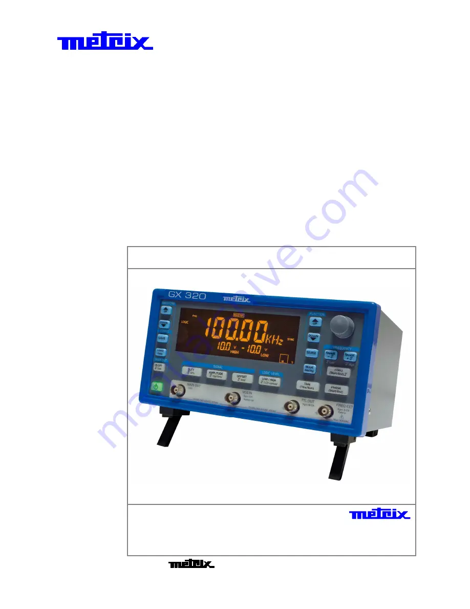
Metrix GX 305 User Manual Download Page 1


 Function 

Generators 

G

G

G

G

G

G

G

G

G

G

G

G

X

X

X

X

X

X

X

X

X

X

X

X


3

3

3

3

3

3

3

3

3

3

3

3

0

0

0

0

0

0

0

0

0

0

0

0

5

5

5

5

5

5

5

5

5

5

5

5


G

G

G

G

G

G

G

G

G

G

G

G

X

X

X

X

X

X

X

X

X

X

X

X


3

3

3

3

3

3

3

3

3

3

3

3

1

1

1

1

1

1

1

1

1

1

1

1

0

0

0

0

0

0

0

0

0

0

0

0


----

----

----


G

G

G

G

G

G

G

G

G

G

G

G

X

X

X

X

X

X

X

X

X

X

X

X


3

3

3

3

3

3

3

3

3

3

3

3

1

1

1

1

1

1

1

1

1

1

1

1

0

0

0

0

0

0

0

0

0

0

0

0

P

P

P

P

P

P

P

P

P

P

P

P


G

G

G

G

G

G

G

G

G

G

G

G

X

X

X

X

X

X

X

X

X

X

X

X


3

3

3

3

3

3

3

3

3

3

3

3

2

2

2

2

2

2

2

2

2

2

2

2

0

0

0

0

0

0

0

0

0

0

0

0


----

----

----


G

G

G

G

G

G

G

G

G

G

G

G

X

X

X

X

X

X

X

X

X

X

X

X


3

3

3

3

3

3

3

3

3

3

3

3

2

2

2

2

2

2

2

2

2

2

2

2

0

0

0

0

0

0

0

0

0

0

0

0

E

E

E

E

E

E

E

E

E

E

E

E


U

U

U

s

s

s

e

e

e

r

r

r

s

s

s


m

m

m

a

a

a

n

n

n

u

u

u

a

a

a

l

l

l


Pôle Test et Mesure de CHAUVIN-ARNOUX  

Parc des Glaisins - 6, avenue du Pré de Challes 

F - 74940 ANNECY-LE-VIEUX 

Tel. +33 (0)4.50.64.22.22 - Fax +33 (0)4.50.64.22.00


Copyright © 


X0321

8E02

 - Ed. 0

1

 - 0

4

/1

4


Summary of Contents for GX 305

Page 1: ...10 0 0 0 0 0 0 0 0 0 0 0P P P P P P P P P P P P G G G G G G G G G G G GX X X X X X X X X X X X 3 3 3 3 3 3 3 3 3 3 3 32 2 2 2 2 2 2 2 2 2 2 20 0 0 0 0 0 0 0 0 0 0 0 G G G G G G G G G G G GX X X X X X...

Page 2: ...ys 16 Pressing keys for less than 1s 17 Pressing keys for more than 1s 18 Chapter IV General commands 19 Commissioning 19 in Normal mode 19 in Version mode 19 in Calibration mode 19 in Autotest mode 1...

Page 3: ...ap p pt t te e er r r I IIX X X FREQ Frequency meter function 44 Connections 44 C C Ch h ha a ap p pt t te e er r r X X X SYNC Synchronisation function GX 320 only 45 Connections 45 Selection of SLAV...

Page 4: ...asurement devices It is designed for indoor use in an level 2 pollution environment at an altitude of less than 2000 m a temperature between 0 C and 40 C and a RH relative humidity of less than 80 up...

Page 5: ...uarantee does not apply in the following conditions inappropriate use of the equipment or use with incompatible equipment one or more changes made to the equipment without prior explicit authorisation...

Page 6: ...usoidal square triangle logical TTL continuous Wave frequency GX 305 0 001 Hz to 5 MHz for the sinus and the square 0 001 Hz to 2 MHz for the triangle GX 310 0 001 Hz to 10 MHz for the sinus and the s...

Page 7: ...0 Description Function Generators II 7 GX 310 Description contd Back face GX 305 GX 310 GX 310P Display USB type B connection Network connection Working voltage indicator Network connection Working vo...

Page 8: ...sure display degree MHz kHz Hz seconds Function selection current function indicator continuous sweep frequency Duty cycle value display Display of the amplitude value Display of the offset value or t...

Page 9: ...Each time the WAVEFORM or FUNCTION is changed the keys that can be assigned to the wheel adjustment blink for 4 seconds if no keys are used at this time the frequency adjustment Freq or FreqSTART is...

Page 10: ...n of LIN or LOG sweep calibration triggering of the selected adjustment step Autotest run the selected test SWEEP function activated in INT assignment of the desired duration setting for carrying out...

Page 11: ...than 1 second assigns the LCD contrast adjustment to the wheel For the SWEEP function pressing the key for more than 1 second switches from FreqSTART to FreqEND and vice versa These keys assign the se...

Page 12: ...ion internal 1 kHz and external 15 kHz Frequency Shift Keying FSK internal 1 kHz and external 1 MHz Phase Shift Keying PSK internal 1 kHz and external 1 MHz BURST function internal or external 1 MHz G...

Page 13: ...rators III 13 GX 320 Description contd Rear panel GX 320 GX 320E Display USB type B connection Network Connection Indication of the working voltage ETHERNET USB type B connection Network Connection In...

Page 14: ...ulse period Num number of pulses Frequency display digit height 20 mm Underscores Indicate to which digit the wheel increments apply during adjustment Unit of measure display degree MHz kHz Hz seconds...

Page 15: ...ng of a set of pulses in BURST mode to triggering the selected test in Autotest mode Sawtooth or triangle sweep type Modulation rate display AM 20 or 80 GATE mode activated display Master synchronisat...

Page 16: ...signed to the wheel adjustment or having no action lit the corresponding adjustment is assigned to the wheel blinking the corresponding adjustment can be assigned to the wheel Each time the WAVEFORM o...

Page 17: ...ing of a set of pulses calibration triggers the selected adjustment step Autotest triggers the selected test SWEEP activated with INTernal source assignment of the wheel to the desired timing adjustme...

Page 18: ...URST function activated INTernal source Pressing the key for more than 1 second is used to switch the number of pulses Num in the pulse generation period Time and vice versa These keys assign the sele...

Page 19: ...of keys used 1 Normal Mode The instrument starts up using the last used configuration By default the factory configuration is restored The key becomes 2 Version Mode The instrument starts up in Versi...

Page 20: ...lugged the instrument restarts using the last backup backup made the last time the device was turned off using the ON STANDBY key In the event of an error the default configuration is loaded Signal si...

Page 21: ...ment function FUNCTION Pressing once displays the list of functions available on the device in the top right hand corner GX 310 GX 320 The cursor indicates the selected function FUNCTION Pressing agai...

Page 22: ...fic wiring is needed for this function For optimal calibration the device must be at operating temperature switched on for 30 minutes before running calibration In addition when in manual mode it is r...

Page 23: ...triangle square and LOGIC CAL 05 calibrates the duty cycle for square and LOGIC CAL 06 sets AM and FM external modulation CAL 07 sets AM modulation for square and LOGIC signals Running adjustments GX...

Page 24: ...your CHAUVIN ARNOUX representative see p 5 Saving settings GX 320 GX 305 310 Pressing saves the calibration The display is cleared once the backup is made It reappears if the calibration is changed Ex...

Page 25: ...un automatically or manually individual selection and running of tests Wiring needed These tests require specific wiring of the device s input output terminals Two wirings are needed When needed they...

Page 26: ...all segment even segment odd segment displays by pressing the MODE key tSt 01 keyboard and key light test you must press all the keys except each time a key is pressed an LCD segment is cleared N 1 w...

Page 27: ...e run 2 situations are possible the test was successful or the test failed If the test succeeded the display shows in automatic mode or in manual mode If the test failed the automatic test stops at th...

Page 28: ...umber if file 3 is empty if file 3 already contains a configuration the data other than frequency is displayed on the screen Pressing another key than or exits the mode without saving Selects files fr...

Page 29: ...en Pressing a key other than exits the mode without making any changes Selects a file from SEt 00 to SEt 15 Set 00 is the factory configuration The screen is updated using the data from the selected f...

Page 30: ...e configuration overwrites the data in the file Enters configuration mode is displayed with the current file number if file 3 is empty if file 3 already contains a configuration the data except freque...

Page 31: ...n be assigned to the wheel blink GX 320 WAVEFORM Pressing once displays the list of available waveforms at the top left of the screen WAVEFORM If the keys are not pressed for 2 seconds or if another k...

Page 32: ...ue adjustment By pressing several times the digit from which wheel increments are added is selected By default the digit to which increments are applied is the unit digit extreme right This setting is...

Page 33: ...heel is not assigned to a setting FREQ not lit or blinking the current frequency value is We want to enter 1st possibility The FREQ key lights The display shows The display shows The display shows The...

Page 34: ...lay shows 2 The display shows The display shows 5 The display shows 3rd possibility The FREQ key lights The display shows 2500 The display shows The display shows Example 2 The wheel is not assigned t...

Page 35: ...z 50 10 to 90 30 to 70 50 or Assignment of the duty cycle to the wheel The key lights Setting the value 1s Forces the duty cycle value to 50 The duty cycle is limited by the frequency turning the whee...

Page 36: ...alternating voltage cannot be 10 V Setting signal logical levels This function is only available if the LOGIC waveform has been selected or Assignment of the logic signal low level to the wheel The ke...

Page 37: ...h an INTernal source the command signal has a frequency of 1 kHz It can be viewed on the generator SWEEP OUT terminal With an EXTernal source the pilot signal is a TTL signal 0 5 V with a frequency of...

Page 38: ...increment will be applied Adjustment of the selected value 1s Passage from FreqSTART adjustment to FreqEND adjustment Setting phases in PSK mode or Assignment of PhaseSTART adjustment to the wheel The...

Page 39: ...in ascending or descending order Remarks When using EXTernal SWEEP the signal level is read at a frequency of 60 kHz This amplitude coded on 256 values is then converted into frequency When using INTe...

Page 40: ...EXTernal source The generated output frequency is proportional according to a linear or logarithmic rule to the voltage on VCF IN GX 305 310 or VCG IN GX 320 The command signal is sampled on 8 bits us...

Page 41: ...on contd Setting the scan time using INTernal source or Displays the Time and assigns adjustment to the wheel The key lights Pressed successively selects the digit to which the increment will apply Ad...

Page 42: ...r 10 V FM the output signal frequency is typically Freqstart for 10 V Freqstart Freqend 2 for 0 V Freqend for 10 V Remarks For AM with LOGIC and square signals modulation is digital the modulating sig...

Page 43: ...quency modulation EXTernal source Display Description Amplitude modulation Frequency modulation Setting START END FM frequencies or Displays FreqSTART and assigns adjustment to the wheel The key light...

Page 44: ...90 mV sensitivity for 80 MHz F 100 MHz The maximum amplitude of the measured signal is 300 V sensitivity from 5 Hz to 5 kHz 30 V sensitivity from 5 kHz to 1 MHz 10 V sensitivity above this value sign...

Page 45: ...z The Master generator supplies the Slave generators with the clock Clk used to generate the signals 10 MHz and a synchronisation signal Ctrl This allows all the generators to start at the same time a...

Page 46: ...at of the slave s related to the master The phase offset entered on the master is applied to all the slaves whereas the phase offset entered on the slave is limited to that slave Phase offset slave ma...

Page 47: ...neration on the master using its MAIN OUT ON OFF key MAIN OUT on the Master Activates MAIN OUT and signal generation on all devices on which MAIN OUT is activated The master key lights Locking slaves...

Page 48: ...nx n where n is always an odd number To synchronise multiple frequencies the values programmed in the DDS must also be multiple We are here faced with the problem of calculation rounding and programmi...

Page 49: ...d amplitude 20 Vpp a null offset a null phase and a frequency of 100 Hz or 99 987 Hz Slave 1 on which the SINE waveform is selected amplitude 6 7 V a null offset a null phase and a frequency of 3 99 9...

Page 50: ...tion MAIN OUT 1s Function activation the indication is displayed the MAIN OUT terminal remains activated The key blinks MAIN OUT 1s Pressing the key for more than 1 second does not activate the MAIN O...

Page 51: ...sing the MODE key The minimum authorised window time is 2 s the number of pulses is defined as follows Nummin F 2 s where Nummin whole number 1 is the minimum number of authorised pulses and F is the...

Page 52: ...plied Value adjustment Pressed successively selects the digit to which the wheel increments will be applied 1s Using an INT source pressing successively for more than 1 second switches from Num to Tim...

Page 53: ...er an A B type USB cable via a USB to UART converter via ETHERNET Warning To use the ETHERNET link the USB cable must be disconnected USB If the CP210x driver is correctly installed on the PC the USB...

Page 54: ...C Set the connection with a terminal Port TELNET 23 to the IP address which has been defined in the generator Straight cable Connect the generator to the PC network through a Hub with the straight ETH...

Page 55: ...e version version date serial number NL with instrument device type GX310 GX320 programmable P if the GX 310 device is programmable E if the GX 320 device is programmable firmware version software ver...

Page 56: ...e 50 Temperature ratio 20 ppm C Long term derivation 5 ppm an MAIN OUT signal Adjustable amplitude in open circuit from 0 to 20 Vpp Accuracy from 0 1 to 20 Vpp 5 from 1 mHz to 10 MHz 1 5 dB for F 10 M...

Page 57: ...om an input power surge 60 VDC 40 VAC SWEEP scan function Frequency resolution 0 28 Hz 10 mHz or 1 mHz depending on the selected range depending on entered FreqSTART FreqEND and Time Linear Mode LIN o...

Page 58: ...and an amplitude allowing to select a modulation at 20 and 80 of the total programmed amplitude EXTernal source modulation using an amplitude signal between 10 V on the BNC VCG IN with a frequency of...

Page 59: ...riggered manually MODE key Trigger delay of approx 1 5 s GATE Function GX 320 only Authorisation to output the alternating component of the MAIN OUT signal using a TTL signal with a frequency of 2 MHz...

Page 60: ...re 20 C to 70 C 10 to 95 RH Use indoor Altitude 2000 m Relative Humidity 80 up to 31 C Power supply Mains Voltage 230 V 10 115 V 10 hardware voltage selection Frequency 50 60 Hz Consumption 20 VA max...

Page 61: ...cal Specifications Function Generators XV 61 Mechanical Specifications Mechanical specifications Box Size support folded length 190 mm width 227 mm height 130 mm Weight 2 850 kg Packaging 330 x 260 x...

Page 62: ...uages Programming instructions in 2 languages USB CP210x USB to UART Bridge Controller USB Drivers LabView and LabWindows Drivers USBxPress application USB port identification GX320E Admin application...

Reviews: