


27
13.7
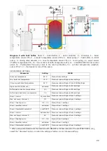
Wiring diagram
Controller wiring diagram
: BT - CT4 boiler temperature sensor, RS - CT4 boiler return water temperature
sensor, CWU - CT4 hot usable water temperature sensor, FS - feeder temperature sensor, BH - top buffer
temperature sensor, BL - bottom buffer temperature sensor, H - voltage output for controlling the auxiliary
boiler, or alarm signalling, or hot usable water circulation pump, RELAY - relay, M1 - CT4 regulated circuit
(mixer 1) temperature sensor, M2 - CT4 regulated circuit (mixer 2) temperature sensor, WS - CT6-P
weather sensor, FT - CT2S exhaust temperature sensor, BP - control panel, B - additional heating circuits
control module, λ - lambda probe module, RP - ecoSTER TOUCH room panel with a room thermostat
function, RT - no/nc room thermostat, RPM - circulation pump control output, DS - fuel container cover or
door opening sensor input.
L N PE - 230V~ power supply, STB - temperature limit switch input, FH - fan, FA - main feeder, FL - hot
usable water circulation pump, BP - boiler or buffer loading pump, DH - hot usable water pump, PM - mixer
pump, SM - mixer actuator, IG - igniter, CPU - controller.
Summary of Contents for ecoMAX860P2-T
Page 2: ...2...
Page 6: ......
Page 7: ...REGULATOR INSTRUCTION MANUAL ecoMAX860P2 T...
Page 19: ...19 CONTROLLER INSTALLATION AND SERVICE SETTINGS MANUAL ecoMAX860P2 T...
Page 43: ......
Page 44: ......
Page 45: ......
Page 46: ......
Page 47: ......


