


30
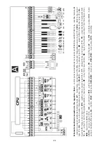
annunciator, 3 – relay RM 84-2012-35-1012
RELPOL and base GZT80 RELPOL.
12.14
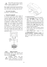
Connection of mixer
When connecting mixer servo,
take due care to prevent boiler
overheating, which may occur
when the flow of boiler water is
limited. You are advised to get
familiar with the position of the
valve
corresponding
to
its
maximum
opening
before
commencement of work so that
you may ensure heat collection
from the boiler at any time it is
required by opening it completely.
The regulator works only with mixing valve
servos equipped with limit switches. Use of
other servos is not allowed. The servos of full
turn time from 30 to 255 s may be used.
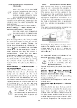
Description of mixer connection:
- connect mixer temperature sensor, -
connect mixer pump wiring,
- switch on the regulator and select proper
Mixer support in the service menu
Service settings
Mixer 1 Settings
- enter the proper Valve opening time in (this
time should be indicated on servo rating
plate e.g. 120 s).
- connect power supply to the regulator and
switch on the regulator to start the mixer
pump,
- determine direction of servo closing/
opening. For this purpose, set the selector
located on the housing of the servo to
manual control and find the positions in
which the temperature in mixer circuit is
maximum and minimum (it corresponds to
the setting of the regulator of "100% ON"
and "0% OFF, respectively). Note the
position to verify the connections later,
- disconnect power supply to the regulator,
- connect mixer servo and regulator wiring
according to valve servo manufacturer's
technical documentation. Do not mistake
direction of valve opening with its closing,
- connect regulator power supply,
- check whether wires to mixer closing and
opening are not interchanged. To do this,
enter MENU Manual control and open the
mixer by selecting Mix1 Open = ON. When
opening the servo, the temperature on mixer
sensor should increase. If not, disconnect
regulator power supply and switch the wires.
Note: Other reason may be incorrect
mechanical connection of the valve! – refer
to the documentation of valve manufacturer
and check whether the valve is properly
connected.
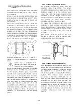
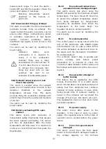
12.15
Connecting temperature
limiter STB
When temperature of water in the boiler
exceeds 95°C, power supply of the electric
feeder and the fan is cut off by the safety
temperature limiter. To reset the limiter it is
needed to press the button placed in the side
of the casing, near the power switch.
Pressing of that button is only possible when
temperature of water in the boiler drops.
If the regulator is not factory-equipped with
the safety temperature limiter, the STB
should be connected as an external device.
The STB temperature limiter should be
connected to the 1-2 terminals shown on the
electric scheme. If the safety temperature of
water in the boiler exceeds, the power supply
of the fan and the engine of feeder will be
cut off by the temperature limiter.
Safety temperature limiter should
have nominal operation voltage of
~230V and should follow current
regulations.
Warning: 1-2 terminals are under
dangerous voltage.
12.16
DS input
There is a possibility of connecting the sensor
that detects a door or fuel tank flap opening.
Opening of the DS contact results in
disconnection of the fan and the feeder
power supply. DS connector is under safe
voltage.
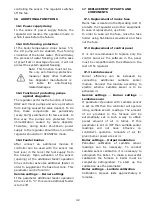
12.17
Connecting room panel
The regulator can be equipped with room
panel ecoSTER TOUCH, which can serve as:
- room thermostat,
- boiler control panel,
- alarm signalling device,
- fuel level indicator.
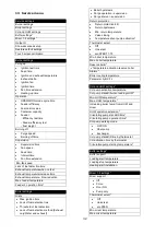
Summary of Contents for ecoMAX860P TOUCH
Page 2: ......
Page 6: ...6...
Page 7: ...INSTRUCTION MANUAL ecoMAX 860P TOUCH...
Page 17: ...INSTALLATION AND SERVICE SETTINGS ecoMAX 860P TOUCH...
Page 43: ......