


29
the value set in the parameter of Reserve
boiler activation temperature, the regulator
stops to supply voltage to the output H, and
the reserve boiler switches on.
Entry of the regulator to “Boiler
switch off” conditions causes the
reserve boiler switches on.
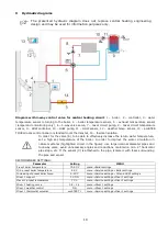
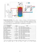
Hydraulic diagram with the reserve boiler,
connection of open and close circuits 1 –
regulator, 2 – reserve boiler, 3 – U3 module (2
pcs), 4 – switching valve (with limit switches), 5 –
heat exchanger (recommended settings: HUW
mode = No priority, Heat exchanger = ON.
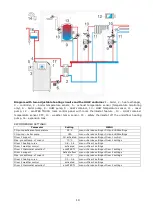
Hydraulic diagram with the reserve boiler and the
4-way valve in close circuit 1 – regulator, 2 –
reserve boiler, 3 – U3 module, 2 pcs., 4 –
switching valve servo (with limit switches) - to
ensure free gravitational flow of water in the
boiler circuit, active cross-section of switching
valve (4) has to be larger than or equal to cross-
section of boiler circuit pipes. Use pipes of large
cross section for gravitational boiler circuit.
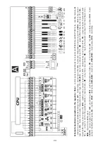
Electric diagram for switching valve of the reserve
boiler, where: 1 – regulator, 2 – reserve boiler,
3,4 – relay RM 84-2012-35-1012 RELPOL and
base GZT80 RELPOL, 5 – servo of switching valve.
12.13
Connection of alarm
signaling
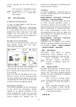
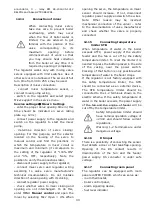
The regulator may announce an alarm
condition by activating external device (e.g.
bell or GSM device to send SMS). Alarm
signaling and reserve boiler control use the
same terminals, therefore, setting of the H
output for alarm signaling deactivates the
function of reserve boiler control. Connect
alarm annunciator through U3 module.
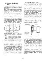
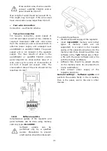
Connection of an external alarm annunciator 1 -
regulator - module A, 2 – external alarm
Summary of Contents for ecoMAX860P TOUCH
Page 2: ......
Page 6: ...6...
Page 7: ...INSTRUCTION MANUAL ecoMAX 860P TOUCH...
Page 17: ...INSTALLATION AND SERVICE SETTINGS ecoMAX 860P TOUCH...
Page 43: ......